EasyManua.ls Logo

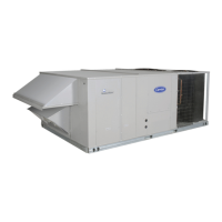
Carrier 50TFF007-014 - User Manual

Carrier 50TFF007-014
44 pages
To Next Page IconTo Next Page
Loading...
Copyright 2000 Carrier Corporation Form 50TFF-C1PD
Single-Package Rooftop Units with:
Galvanized pre-painted steel
cabinet
Fifty-one mm (2-in.) return-air filters
Commercial strength base rails
Exclusive tool-less filter access
panel
Corrosion-resistant sloped
condensate pan
Single power entry to unit
Commercial duty motors with
permanently lubricated bearings
Standard cooling operation at
outdoor ambient temperatures as
low as –4 C (25 F)
Meets ASHRAE Standard 62
(Indoor Air Quality)
Features/Benefits
Compact, vertical discharge
units convert to horizontal
discharge, combining
installation flexibility with
efficient performance and
easy maintenance.
Easy installation and
conversion
All units are shipped in the vertical dis-
charge configuration for fit-up to
standard roof curbs. (Two different curb
sizes fit unit sizes 007 and 008-014.)
The contractor can order and install the
roof curb early in the construction
stage, before decisions on size require-
ments are made.
All units feature roll-formed baserail
design with forklift slots on 3 sides and
rigging holes for easier maneuvering.
Durable packaging protects all units
during shipment and storage.
The units can be easily converted
from a vertical to a horizontal
discharge configuration by interchang-
ing the panels supplied with the unit.
50TFF007-014
Single-Package Rooftop Units
Electric Cooling
with Electric Heat Option
50 Hz
Nominal Capacity: 17.6 kW to 35.9 kW
(5 to 10.2 Tons)
Product
Data
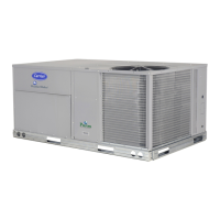
50TFF007
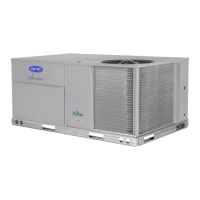
50TFF008-014
Question and Answer IconNeed help?

Do you have a question about the Carrier 50TFF007-014 and is the answer not in the manual?

Carrier 50TFF007-014 Specifications

General IconGeneral
BrandCarrier
Model50TFF007-014
CategoryAir Conditioner
LanguageEnglish

Summary

Product Data

50 TFF007-014 Single-Package Rooftop Units Electric Cooling with Electric Heat Option 50 Hz

Main product identification and specifications for the unit series.

Nominal Capacity: 17.6 kW to 35.9 kW (5 to 10.2 Tons)

Specifies the cooling capacity range in kW and Tons.

Features;Benefits

Features;Benefits (cont)

The Apollo communicating control is factory-installed...

Further details on the Apollo control's capabilities and integration.

Model number nomenclature

Explanation of how to interpret the unit's model number.

Carrier Apollo controls add reliability, efficiency, and simplification

Benefits of the factory-installed Apollo direct digital controls.

Physical data (SI)

Physical data (English)

UNIT SIZE 50 TFF

Lists physical specifications for each unit size in English units.

Options and accessories

Apollo Communicating Controls

Option for advanced communication and control systems.

EconoMi$er

Option for economizer operation to save energy.

Electric Heat

Option for electric heating capability.

HEAD PRESSURE CONTROL

Options and accessories (cont)

FACTORY-INSTALLED APOLLO COMMUNICATING CONTROLS

Explanation of the Apollo direct digital controls system.

ELECTRIC HEATER

Information about available electric heaters.

Base unit dimensions - 50 TFF007

Base unit dimensions - 50 TFF008-014

Selection procedure (with 50 TFF012 example) - SI

Selection procedure (with 50 TFF012 example) - English

I. Determine cooling and heating requirements at design conditions.

Steps to determine cooling and heating needs in English units.

II. Select unit based on required cooling capacity.

How to choose the correct unit size based on capacity in English units.

III. Select electric heat:

Guidance on selecting electric heat capacity in English units.

IV. Determine fan speed and power requirements at design conditions.

Calculating fan speed and power needs in English units.

V. Determine net capacities.

Adjusting gross capacities for fan motor heat in English units.

Performance data

COOLING CAPACITIES SI

Tables showing cooling capacity based on air temperatures (SI).

Performance data (cont)

COOLING CAPACITIES SI (cont)

Cooling capacity tables in SI units for the largest models.

COOLING CAPACITIES - ENGLISH

Cooling capacity tables in English units.

FAN PERFORMANCE (SI) VERTICAL DISCHARGE UNITS

Fan performance data for vertical discharge in SI units.

FAN PERFORMANCE (SI) HORIZONTAL DISCHARGE UNITS

Fan performance data for horizontal discharge in SI units.

FAN PERFORMANCE (ENGLISH) VERTICAL DISCHARGE UNITS

Fan performance data for vertical discharge in English units.

FAN PERFORMANCE (ENGLISH) - HORIZONTAL DISCHRGE UNITS

Fan performance data for horizontal discharge in English units.

LEGEND AND NOTES FOR COOLING CAPACITY TABLES - SI

Legends and notes for SI cooling capacity tables.

COOLING CAPACITIES ENGLISH (cont)

COOLING CAPACITIES ENGLISH (cont)

Continuation of cooling capacity tables in English units.

LEGEND AND NOTES FOR COOLING CAPACITY TABLES - ENGLISH

Legends and notes for English cooling capacity tables.

FAN PERFORMANCE (SI) VERTICAL DISCHARGE UNITS (cont)

FAN PERFORMANCE (SI) VERTICAL DISCHARGE UNITS (cont)

Continuation of SI fan performance for vertical discharge.

FAN PERFORMANCE (SI) - HORIZONTAL DISCHARGE UNITS (cont)

FAN PERFORMANCE (SI) - HORIZONTAL DISCHARGE UNITS (cont)

Continuation of SI fan performance for horizontal discharge.

FAN PERFORMANCE (ENGLISH) - VERTICAL DISCHARGE UNITS (cont)

FAN PERFORMANCE (ENGLISH) - VERTICAL DISCHARGE UNITS (cont)

Continuation of English fan performance for vertical discharge.

FAN PERFORMANCE (ENGLISH) HORIZONTAL DISCHARGE UNITS (cont)

FAN PERFORMANCE (ENGLISH) HORIZONTAL DISCHARGE UNITS (cont)

Continuation of English fan performance for horizontal discharge.

EVAPORATOR-FAN MOTOR PERFORMANCE

FAN R;S AT MOTOR PULLEY SETTINGS* (SI)

Fan speed (r/s) based on motor pulley settings in SI units.

FAN RPM AT MOTOR PULLEY SETTINGS* (ENGLISH)

Fan speed (RPM) based on motor pulley settings in English units.

ACCESSORY;FIOP STATIC PRESSURE DROP (Pa) - 50 TFF007

ELECTRIC HEATING CAPACITIES

Electric heating capacities for different unit sizes.

Electrical data

UNIT

Detailed electrical data for each unit size.

Typical wiring schematic (50 TFF008-014 shown)

SCHEMATIC

Detailed wiring schematic for the unit.

LEGEND

ECON

Explanation of Economizer.

Controls

Operating sequence

Sequence of operations for cooling without economizer.

Cooling, units with Durablade economizer

Operating sequence for cooling with Durablade economizer.

Cooling, units with EconoMi$er (50 TFF007)

Operating sequence for cooling with EconoMi$er (50TFF007).

Cooling, units with EconoMi$er (50 TFF008-014)

Operating sequence for cooling with EconoMi$er (50TFF008-014).

Controls (cont)

If outdoor-air alone cannot satisfy the cooling requirements...

Further details on economizer operation and cooling sequences.

Heating, units with economizer (If Accessory Heater is Installed)

Operating sequence for heating with economizer and heater.

Application data

Minimum ambient cooling operating temperature

Operational limits for cooling at low ambient temperatures.

Related product manuals