3
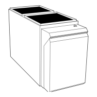
DIMENSIONS
A
[736.9]
29
Ø7/8
[22.2]
ACCESSORY
5 15/16
[150.7]
28.39
[721.2]
Ø7/8
[22.2]
ACCESSORY
14 7/8
[337.3]
(BOTH SIDES)
Ø7/8
[22.2]
ACCESSORY
Ø7/8
[22.2]
ACCESSORY
Ø1 3/4
[44.5]
GAS ENTRY
Ø1/2
[12.7]
THERMOSTAT WIRE ENTRY
22 1/16
[560]
SIDE INLET
(BOTH SIDES)
11 7/16
[290.7]
9 11/16
[245.4]
[197.8]
7 13/16
Ø7/8
[22.2]
J.BOX PROVISION
Ø7/8
[22.2]
JUNCTION BOX
LOCATION
Ø1 3/4
[44.5]
GAS ENTRY
1 15/16
[49.2]
[25.4]
1 1/4
[31.8]
29 9/16
[750.7]
1 15/16
[49.2]
5 5/8
[143.3]
5 7/16
[138.5]
6 13/16
[172.3]
Ø1/2
[12.7]
THERMOSTAT WIRE ENTRY
19
[481.7]
OUTLET
21.6
[549.5]
BOTTOM INLET
33 1/4
[843.9]
9 9/16
[243.3]
3/4
[19.1]
5 7/8
[148.5]
3 7/16
[86.8]
9 7/8
[250.7]
27 3/4
[704.7]
2 5/16
[59]
FRONT OF CASING
TOP OF CASING
4 13/16
[122.2]
27 3/4
[704.7]
5 7/8
[148.5]
8 5/8
[219]
5 1/2
[140.3]
8 7/16
[213.5]
FRONT OF CASING
TOP OF CASING
6.1
[155.7]
2 1/16
[51.6]
5.1
[130.5]
1.7
[43.5]
Ø7/8
[22.2]
ACCESSORY (2)
AIR FLOW
AIR FLOW
BOTTOM RETURN
WIDTH
AIR FLOW
KNOCK OUTS FOR
VENTING(5
PLACES)
A10270
NOTES:
1. Two additional 7/8 ---in. (22 mm) diameter holes are located in the top plate.
2. Minimum return---air openings at furnace, based on metal duct. If flex duct is used, see flex duct manufacturer’s recommendations for equivalent diameters.
a. For 800 CFM ---16 ---in. (406 mm) r o und or 14 1/2 x 12 ---in. (368 x 305 mm) rectangle.
b. For 1200 CFM---20---in. (508 mm) round or 14 1/2 x 19 1/2---in. (368 x 495 mm) rectangle.
c. For 1600 CFM---22---in. (559 mm) round or 14 1/2 x 22 1/16---in. (368 x 560mm) rectangle.
d. For airfl ow requiremen ts above 1800 C FM, see Air Delivery table in Product Data literature for specific use of single side inlets. The use of both sideinlets,
a combination of 1 side a nd the bottom, or the bottom on ly wil l ensur e adequate r etu r n air openings for airflow requirements above 1800 CFM.
A B C D
FURNACE
SIZE
CABINET
WIDTH
OUTLET
WIDTH
TOP AND
BOTTOM FLUE
COLLAR
BOTTOM
INLET WIDTH
VENT
CONNECTION
SIZE
SHIP WT. LB
(KG)
ACCESSORY
FILT ER MEDIA
CABINET SIZE
045---12 14-3/16 (360) 12-9/16 (319) 9-5/16 (237) 12---11/16 (322) 4 (102) 107 (49) 16 (406)
070---16 17 --- 1/2 (445) 15-7/8 (403) 11-9/16 (294) 16 (406) 4 (102) 126 (57) 16 (406)
090--- 16 21 (533) 19-3/8 (492) 13-5/16 (338) 19--- 1/2 (495) 4 (102) 140 (64) 20 (506)
110--- 22 21 (533) 19-3/8 (492) 13-5/16 (338) 19--- 1/2 (495) 4 (102) 152 (69) 20 (506)
135--- 22 24-1/2 (622) 22-7/8 (581 15-1/16 (383) 23 (584) 4 (102) 163 (74) 24 (610)
*135 size furnaces require a 5 o r 6---in. (127 or 152 mm) vent. Use a ven t adapter between fur nace and vent stack. See Installation Instruction s for complete
installation requirements.
EXAMPLE OF MODEL NUMBER NOMENCLATURE
58CTW 045 100 08
58CTW Two-Stage 4- Way Multipoise
Nominal Cooling Size
(Airflow at .5 e.s.p.)
(400 CFM per 12,000 Btuh)
12---1200 CFM
Input Capacity 16---1600 CFM
045---44,000 Btuh 110---110,000 Btuh 22---2200 CFM
070---66,000 Btuh 135---132,000 Btuh 100
090---88,000 Btuh Series Number
58CTW/CTY
 Loading...