38
Table 11 – Electrical Data
UNIT SIZE V O LT S ---
H E R T Z ---
PHASE
OPERATING VOLTAGE
RANGE*
MAXIMUM
UNIT
AMPS
UNIT
AMPACITY#
MINIMUM
WIRE
SIZE
AWG
MAXIMUM
WIRE
LENGTH
FT (M)}
MAXIMUM
FUSE OR CKT
BKR
AMPS{
Maximum* Minimum*
040---10 1 1 5 --- 6 0 --- 1 127 104 7.5 10.3 14 36 (11.0) 15
040---12 1 1 5 --- 6 0 --- 1 127 104 7.5 10.2 14 36 (11.0) 15
060---12 1 1 5 --- 6 0 --- 1 127 104 7.6 10.3 14 36 (11.0) 15
060---14 1 1 5 --- 6 0 --- 1 127 104 9.2 12.4 14 29 (8.8) 15
080---16 1 1 5 --- 6 0 --- 1 127 104 9.2 12.4 14 29 (8.8) 15
080---20 1 1 5 --- 6 0 --- 1 127 104 11.7 15.5 12 37 (11.3) 20
100---20 1 1 5 --- 6 0 --- 1 127 104 11.8 15.6 12 36 (11.0) 20
120---22 1 1 5 --- 6 0 --- 1 127 104 11.8 15.6 12 36 (11.0) 20
* Permissible limits of the voltage range at which the unit operates satisfactorily.
# Unit ampacity = 125 percent of largest operating component’s full load amps plus 100 percent of all other potential operating components’ (EAC, humidifier,
etc.) full load amps.
{Time---delay type is recommended.
}Length shown is as measured one way along wire path between furnace and service panel for maximum 2 percent voltage drop.
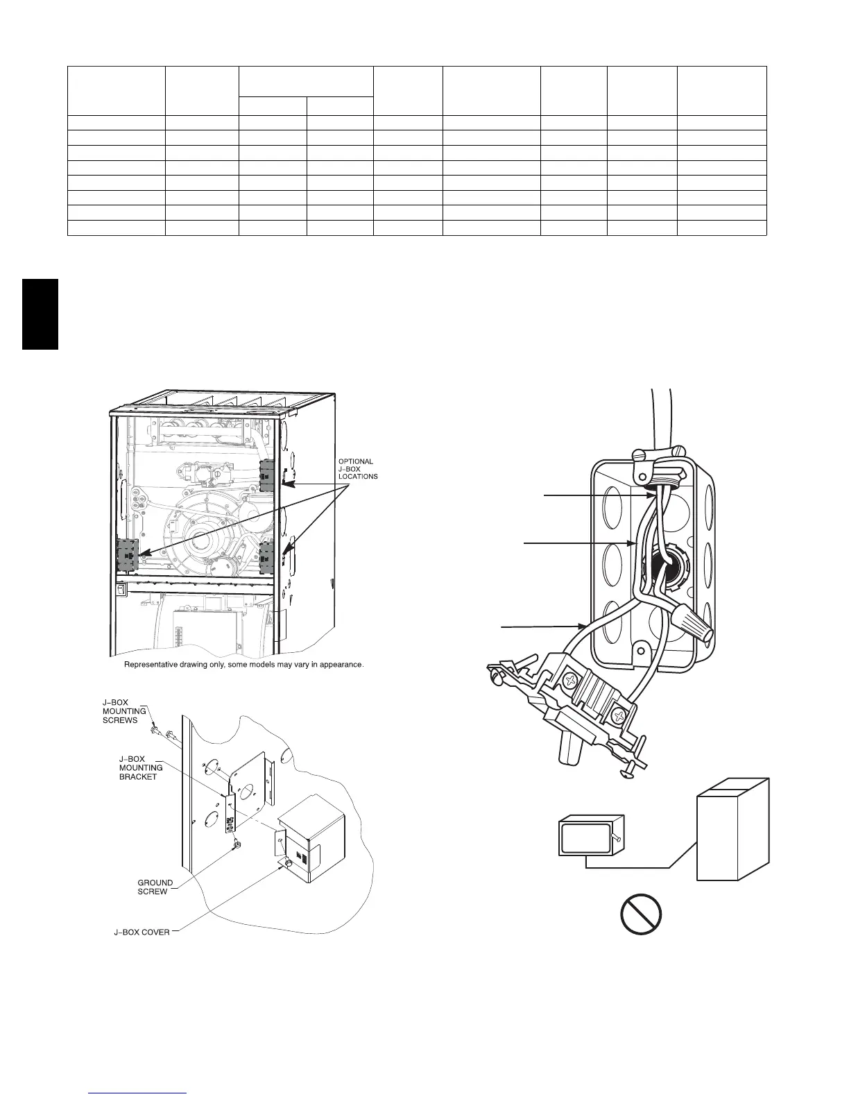
A12226
Fig. 31 -- Installing J--Box (When Used)
COPPER
WIRE ONLY
ELECTRIC
DISCONNECT
SWITCH
ALUMINUM
WIRE
GROUND
NEUTRAL
LINE VOLTAGE
A11146
Fig. 32 -- Field--Supplied Electrical Box on Furnace Casing
59TP6A