72
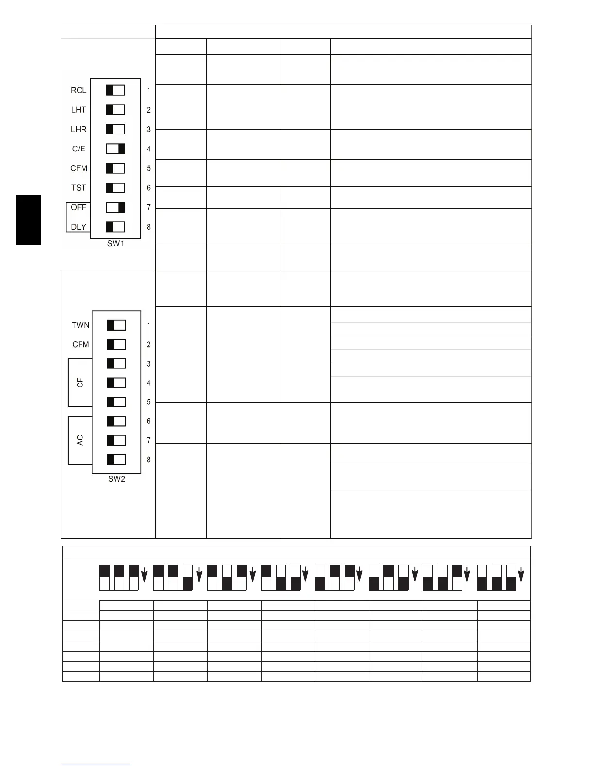
SW1-1 Status Code Recovery OFF
Turn ON to retrieve up to 7 stored status codes for
troubleshooting assistance when R thermostat lead is
disconnected.
Low Heat Only
(Adaptive Heat Mode
when SW1-2 is OFF)
When SW1-2 is OFF allows two-stage operation with a single
stage thermostat. Turn ON when using two- stage thermostat to
allow Low Heat operation when R to W/W1 closes and High Heat
operation when R to W /W1 and W2 close.
Turn ON to increase Low Heat airflow by 18 percent. This
compensates for increased return air temperature caused with
bypass humidifier.
Comfort/Efficiency
Adjustment
Turn ON to decrease low heat airf low by approximately 7 percent
and high heat by approximately 10 percent for maximum comfort
SW1-5 CFM per ton adjust OFF
Turn ON f or 400 CFM per ton, T urn OFF f or 350 CFM per ton.
See also SW2.
SW1-6 Component Self Test OFF
Turn ON to initiate Component Self Test for troubleshooting
assistance when R thermostat lead is disconnected. Turn OFF
when Self Test is completed.
SW1-7 & SW1-8 Blower OFF delay ON or OFF
Blower Off Delay time – adjustable 90 seconds to 180 seconds.
See table in Adjustments section or refer to unit wiring diagram.
Allows for selection of furnace Main (OFF) or Secondary (ON)
when Twinned furnace setup is required. See kit instructions for
further directions on installation and setup.
Allows additional CFM per ton selections when used with SW 1-5
325 CFM per ton (nominal) when SW 2-2 ON and SW 1-5 OFF
350 CFM per ton (nominal) when SW 2-2 OFF and SW 1-5 OFF
370 CFM per ton (nominal) when SW2-2 ON and SW 1-5 ON
400 CFM per ton (nominal) when SW 2-2 OFF and SW 1-5 ON
See Air Delivery Tables for model specific CFM vs. static
pressure
SW 2-6, 7, 8 AC (Cooling Airflow) OFF
The AC setup switches select desired cooling or high stage
cooling (two stage units) airflow. See Cooling Air Delivery Tables
for specific switch settings.
The CF setup switches select desired Continuous Fan Airflow
The CF switch position is the low cooling airflow selection for two
stage cooling units.
The CFM values are shown in the Air Delivery Tables below for
SW 2 settings. SW 2-3, 4, 5 cannot be set f or airf low higher than
SW 2-6, 7, 8. See Continuous Fan Air Flow T able f or specific
switch settings.
Furnace Setup Switch Description
BASED ON 350 CFM/TON (Factory Default: SW1−5 = OFF, SW2−2 = OFF)
Model
Size
ON
ON
ON
ON ON ON
ON ON
5 4 3 5 4 3 5 4 3 5 4 3 5 4 3 5 4 3 5 4 3 5 4 3
040-10 525 525 700 875 875 875 875 875
040-12 525 525 700 875 1050 1050 1050 1050
060-12 525 525 700 875 1050 1050 1050 1050
060-14 525 525 700 875 1050 1225 1225 1225
080-16 525 525 700 875 1050 1225 1400 1400
080-20 875 1225 1400 1750 1750
100-20 875 1050 1225 1400 1750 1750
120-22 875 875 1050 1225 1400 1750 1925
700
700 700
700
700
1050
A14400
Fig. 58 -- Furnace Setup Switch Description
59TP6A