1-1
T -312
SECTION 1
DESCRIPTION
1.1 INTRODUCTION
This manual contains Operating and Service
Instructions and Electrical Data for the Model 68G5-105
Coach Air Conditioning and Heating equipment
furnished by Carrier Transicold Division for the MCI
J-Series Intercity coach. Table 1-1 provides a model
number chart.
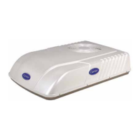
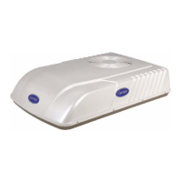
The Model 68G5-105 equipment (see Figure 1-1)
consist of a condenser , a main evaporator with integral
heater, a driver evaporator with integral heater , optional
parcel rack evaporators, compressor assembly, main
control box, driver display panel, check valve assembly,
temperature sensors and a bypass heat valve.
The 68G5 air conditioning and heating equipment
interfaces with electrical cabling, a parcel rack
evaporator thermostat kit, refrigerant piping, engine
coolant piping, ductwork and other components
furnished by the coach manufacturer to complete the
system.
Table 1-1. Part (Model) Number Chart
Model No. Refrigerant Controller Fan Motors Parcel Rack Connection
68G5-105
R-134a
Microprocessor 24VDC Yes
Table 1-2. Additional Support Manuals
MANUAL/FORM NUMBER EQUIPMENT COVERED TYPE OF MANUAL
62--02756 O5G Compressor Operation and Service
T--200PL O5G Compressor Parts List
T--279PL MCI E/J Coach Parts List
Compressor
Assembly
Condenser
Main Evaporator
Driver Evaporator
Parcel Rack Evaporator
Main Control Box
Check
Valve
Driver Display
Panel
*Bypass
Heat
Valve
Roadside Return Air
Temperature Sensor
Curbside Return Air
Temperature and
Humidity Sensor
*Driver Evaporator
Control Box
*INDICATES COMPONENTS FURNISHED
BY THE COACH MANUFACTURER
Figure 1-1. Coach Cutaway View

 Loading...


