3–1 T-359
SECTION 3
DESCRIPTION
3.1 GENERAL DESCRIPTION
3.1.1 Refrigeration Unit - Front Section
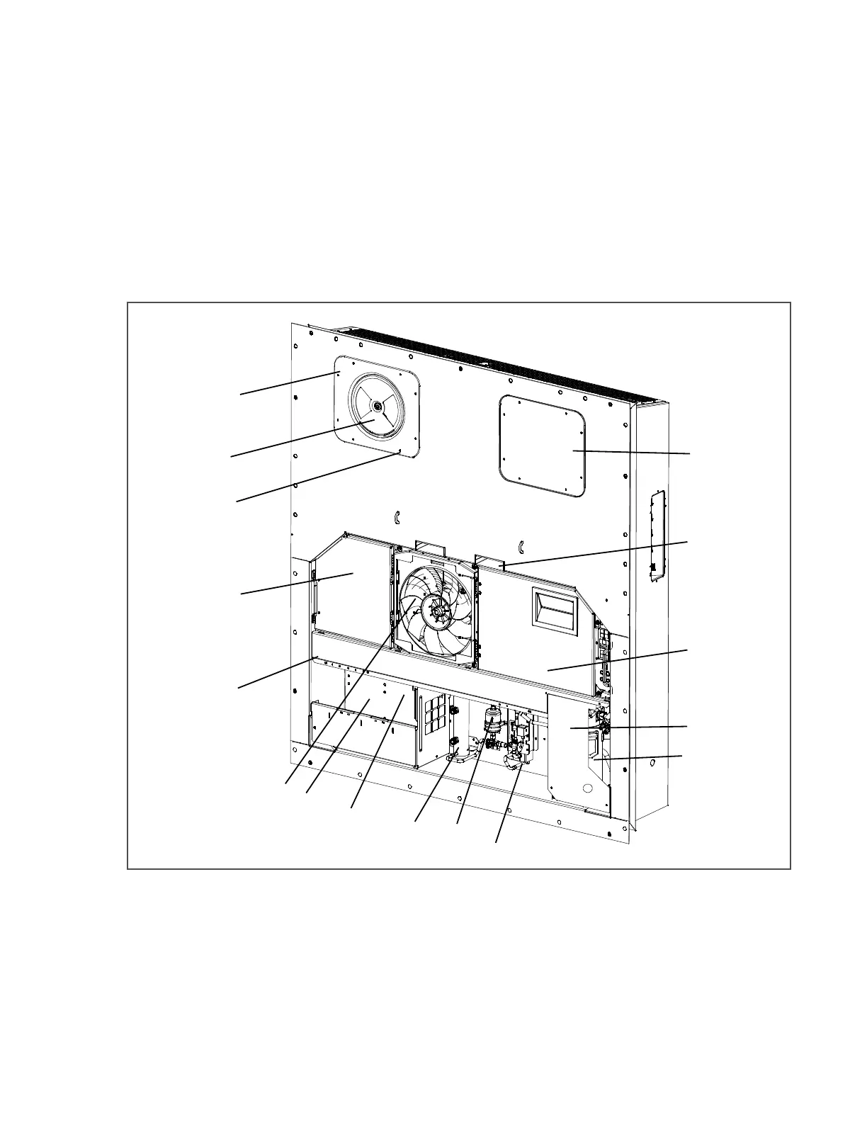
The unit is designed so that the majority of the components are accessible from the front (see Figure 3.1). The unit
model number, serial number and parts identification number can be found on the serial plate to the left of the
receiver on the back wall of the condenser section.
3.1.2 Fresh Air Makeup Vent
The function of the upper makeup air vent is to provide ventilation for commodities that require fresh air circulation.
A manually operated venting system is located in the upper left access panel.
Figure 3.1 Refrigeration Unit - Front Section
1. Access Panel (Evap. Fan #1)
2. Fork Lift Pockets
3. Control Box
4. Compressor Cover
5. Compressor
6. Economizer
7. Filter Drier
8. Receiver
9. Unit Serial Number, Model Number and
Parts Identification Number (PID) Plate
10. Power Cables and Plug (Location)
11. Condenser Fan
12. Interrogator Connector (Front left)
13. Temperature Recorder (Provisioned)
14. TIR (Transports Internationaux Routiers)
Sealing Provisions - Typical All Panels
15. Upper Fresh Air Makeup Vent Panel
16. Access Panel (Evap. Fan #2)
- - - - -

 Loading...


