26
LEGEND FOR FIG. 3-19
Main Base Board (MBB)
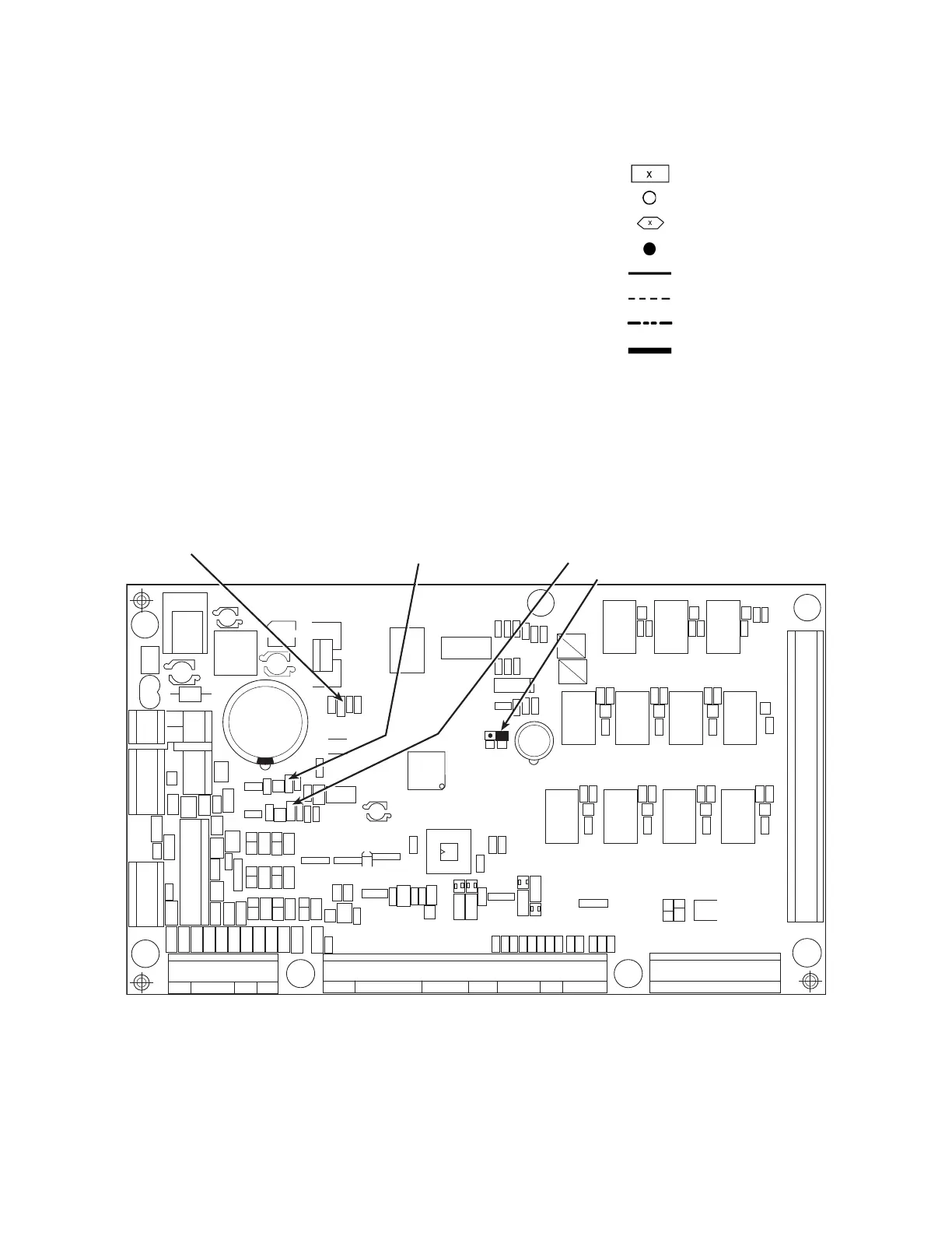
See Fig. 20. The MBB is the heart of the ComfortLink control sys-
tem. It contains the major portion of operating software and con-
trols the operation of the machine. The MBB continuously moni-
tors input/output channel information received from its inputs and
from all other modules. The MBB receives inputs from the dis-
charge and suction pressure transducers and thermistors. See
Table 5. The MBB also receives the feedback inputs from each
compressor current sensor board and other status switches. See
Tables 6 and 7. The MBB also controls several outputs. Relay out-
puts controlled by the MBB are shown in Tables 8 and 9. Informa-
tion is transmitted between modules via a 3-wire communication
bus or LEN (Local Equipment Network). The CCN (Carrier Com-
fort Network) bus is also supported. Connections to both LEN and
CCN buses are made at the LVT (low voltage terminal). See
Fig. 20 and 21.
Fig. 20 — Main Base Board
ALMR — Alarm Relay FCB — Fan Circuit Breaker SW — Switch
AUX — Auxiliary FIOP — Factory-Installed Option TB — Terminal Block
BR — Boiler Relay FR — Fan Relay TNKR — Storage Tank Heater Relay
C — Contactor, Compressor FU — Fuse TRAN — Transformer
CB — Circuit Breaker FVFD Fan Variable Frequency Drive UPC — Unitary Protocol Converter
CCB — Compress
or Circuit Breaker GND — Ground VFD — Variable Frequency Drive
CH — Crankcase Heater HPS — High-Pressure Switch
Terminal Block
CHC — Cooler/Pump Heater Contactor HR — Heat Relay
COMP — Compressor LON — Local Operating Network
Terminal (Unmarked)
CSB — Current Sensor Board LVT — Low Voltage Terminal Block
CWFS — Chilled Water Flow Switch LWT — Leaving Water Temperature
Terminal (Marked)
CWP — Chilled Water Pump MBB — Main Base Board
CXB — Compr
essor Expansion Board MLV — Minimum Load Valve
Splice
DGS — Digital Scroll Compressor MM — Motormaster
DPT — Discharge Pressure Transducer MP — Motor Protector
Factory Wiring
DTT — Discharge Temperature Thermistor MS — Manual Starter
DUS — Digital Unloader Solenoid NEC — National Electrical Code
Field Wiring
EMM — Energy Management OAT — Outdoor-Air Thermistor
EWT — Entering Water Temperature OFM — Outdoor Fan Motor
Accessory or Option Wir
ing
EXV — Electronic Expansion Valve RGT — Return Gas Thermistor
FB — Fuse Block SCCR — Short Circuit Current Rating
To indicate common potential
only; not to represent wiring.
FC — Fan Contactor SPT — Suction Pressure Transducer
CEPL130346-01
STATUS
LEN
J1
J2
J4
J3
J5
J6
J7
J8
J9
J10
CCN
RED LED - STATUS GREEN LED -
LEN (LOCAL EQUIPMENT NETWORK)
YELLOW LED -
CCN (CARRIER COMFORT NETWORK)
INSTANCE JUMPER
K11
K10 K9
K8
K7
K6
K5
K4
K3 K2
K1
2 1
 Loading...