31
Loss-of-Cooler Flow Protection
A proof-of-cooler flow device is factory installed in all chillers. It
is recommended that proper operation of the switch be verified on
a regular basis.
Electronic Expansion Valves (EXVs)
All units are equipped from the factory with EXVs. Each refriger-
ation circuit is also supplied with a factory-installed liquid line fil-
ter drier and sight glass.
The EXV is set at the factory to maintain 9°F (5.0°C) suction su-
perheat leaving the cooler by metering the proper amount of re-
frigerant into the cooler. The superheat set point is adjustable, but
should not be adjusted unless absolutely necessary.
The EXV is designed to limit the cooler saturated suction
temperature to 50°F (12.8°C). This makes it possible for unit to
start at high cooler fluid temperatures without overloading the
compressor.
Capacity Control
The control system cycles compressors, digital scroll modulating
solenoid (if equipped), and minimum load valve solenoids (if
equipped) to maintain the user-configured leaving chilled fluid
temperature set point. Entering fluid temperature is used by the
main base board (MBB) to determine the temperature drop across
the cooler and is used in determining the optimum time to add or
subtract capacity stages. The chilled fluid temperature set point
can be automatically reset by the return fluid temperature, space,
or outdoor-air temperature reset features. It can also be reset from
an external 4 to 20 mA signal (requires energy management mod-
ule FIOP or accessory).
The standard control has an automatic lead-lag feature built in
which determines the wear factor (combination of starts and run
hours) for each compressor. If all compressors are off and less than
30 minutes has elapsed since the last compressor was turned off,
the wear factor is used to determine which compressor to start
next. If no compressors have been running for more than 30 min-
utes and the leaving fluid temperature is greater than the saturated
condensing temperature, the wear factor is still used to determine
which compressor to start next. If the leaving fluid temperature is
less than the saturated condensing temperature, then the control
will start either compressor A1 or compressor B1 first, depending
on the user-configurable circuit lead-lag value. For units with the
minimum load control valve, the A circuit with the minimum load
valve is always the lead circuit. The A circuit is also always the
lead for units with the digital compressor option. On units with the
digital scroll option, the A1 compressor operates continuously,
providing close leaving chilled water control. For this reason, on/
off cycling of the unit’s compressors is dramatically reduced,
which in turn reduces wear associated with compressor start/stop
cycles.
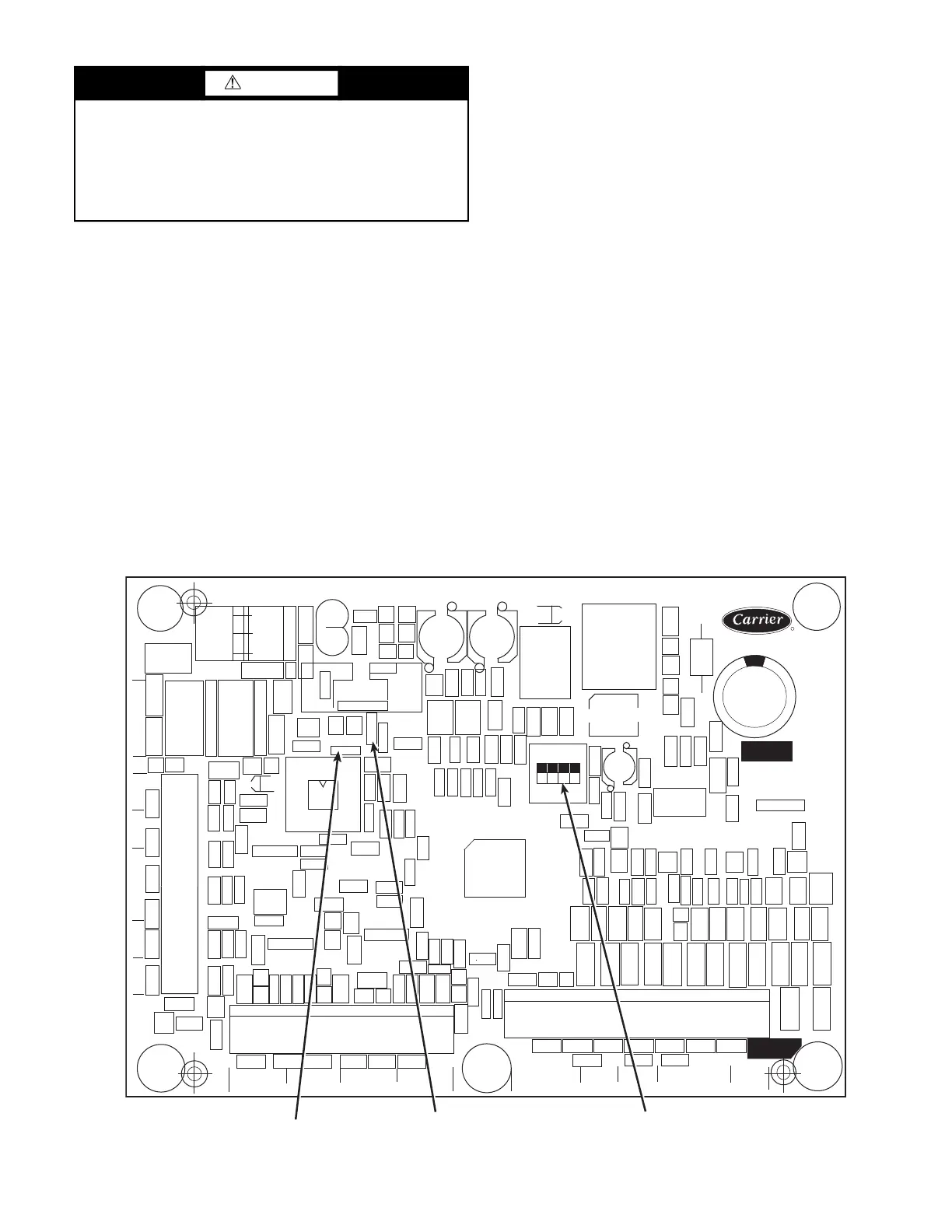
Fig. 26 — Energy Management Module
CAUTION
Care should be taken when interfacing with other manufac-
turer’s control systems due to possible power supply differ-
ences, full wave bridge versus half wave rectification. The two
different power supplies cannot be mixed. ComfortLink con-
trols use half wave rectification. A signal isolation device
should be utilized if a full wave bridge signal generating
device is used.
CEBD430351-0396-01C
TEST 1
CEPL130351-01
PWR
TEST 2
J1
J2
J4 J3
J5
J6
J7
LEN
STATUS
RED LED - STATUS
GREEN LED -
LEN (LOCAL EQUIPMENT NETWORK)
ADDRESS
DIP SWITCH
 Loading...