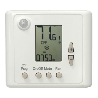
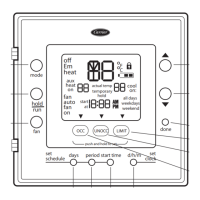
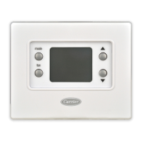
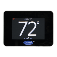
ComfortVu™ BACnet Thermostat Model Standard TB-HM (Line voltage)Carrier Proprietary and Confidential CARRIER CORPORATION ©2020
Installation and Operation Guide All rights reserved
36
Wiring and DIP Switch configurations 31 to 34 – FC systems - 4-pipe
Config. 31:
4-Pipe, 1/2/3 Speeds
fan
(1)
Config. 32:
4-Pipe, 1/2/3 Speeds
fan
(1)
, Floor heating
Config. 33:
4-Pipe, 1/2/3 Speeds
fan
(1)
, Cool valve PID
Config. 34:
4-Pipe, 1/2/3 Speeds
fan
(1)
, Cool valve PID,
Floor heating
Fan medium
(or Economizer
(5)
)
Fan medium
(or Economizer
(5)
)
Fan medium
(or Economizer
(5)
)
Fan medium
(or Economizer
(5)
)
Heat element
(2)
(2nd stage heat)
Floor heating
(1st stage heat-no fan)
Heat element
(2)
(2nd stage heat)
Floor heating
(1st stage heat–no
fan)
Heat valve
(1st stage heat)
Heat valve
(2nd stage heat)
Heat valve
(1st stage heat)
Heat valve
(2nd stage heat)
(1)
SW3.1, SW3.2 – Fan speeds:
1 speed (Low):
2 speeds(Low and High):
3 speeds(Low, Medium, and High):
SW3.1 = ON, SW3.2 = OFF
SW3.1 = OFF, SW3.2 = ON
SW3.1 = OFF, SW3.2 = OFF
(2)
SW3.4 – 2nd heating stage:
ON = Enable, OFF = Disable
(3)
SW3.5 – Chilled beam option:
ON = Enable chilled beam (fan will not run with cooling)
(4)
SW1.3 = Dehumidification:
ON – Use dehumidifier, OFF – Use reheat for dehumidification
(5)
SW1.6–Terminal 12 operation:
ON = Economizer
OFF = Fan Medium (3 speeds) / Terminal not in use (1/2 speeds/VFS)
Important: Economizer will not work in 3 fan speeds configuration.
See drawing for DIP switch and jumper locations (page 24).
Fan on/off: 110-230VAC, 2.5A max., PID valves: 0-10VDC, 0.5mA Not isolated
Control - Heat elements, Cool/Heat valves, Economizer: 110-230VAC, 0.3A max.
 Loading...

