5
Fig. 8 — Attach Relief Damper Hood Assembly to
Return Duct
14. Remove the indoor blower access panel and the panel(s)
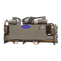
covering the unit control box. (See Fig. 9.)In the hardware kit
provided with the EconoMi$er X is the HH63AW002 con-
troller (Honeywell W7220). Mount the controller assembly
on the left side of the unit control box. Screw controller to the
control box through pre-punched holes in control box. (See
Fig.10.)
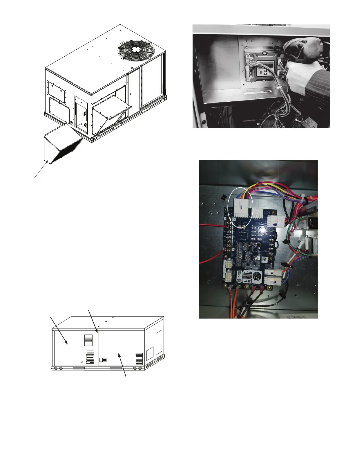
15. Unplug the 12-pin female ECON plug currently connected to
the Unit Control Board (UCB). (See Fig. 11.)
16. Connect the 12-pin female ECON plug removed from the
UCB to the 12-pin male plug from the controller harness.
Refer to Fig. 12 and wiring diagram on page 7.
17. Connect the 12-pin female plug from the controller harness to
ECON on the UCB. Refer to Fig. 13 and wiring diagram on
page 7.)
Fig. 9 — Typical Indoor Fan Motor Access Panel
Locations
Fig. 10 — Mount Controller Assembly in
Unit Control Box
Fig. 11 — Unplug ECON plug from Unit Control Board
Unit Control
Box Panel(s)
Center Post
Indoor Blower
Access Panel
NOTE: Some control box configurations may differ.
 Loading...