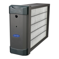
WIRING CONNECTIONS FOR FURNACES
3
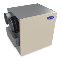
WIRING CONNECTIONS FOR FAN COILS
4
A. Route the power conduit from the purier to a knockout on the fan coil air
handler that provides access to the incoming power wiring compartment.
Afx the end of the conduit to the fan coil air handler using the included
conduit tting.
B. Remove the yellow and black primary wires from the fan coil air handler
transformer terminals and connect the quick connect “piggyback” terminals
of the quick connect kit leads exiting the air purier power conduit assembly
to the transformer terminals. Reconnect the yellow and black primary wires to
their respective transformer terminals on the “piggyback” terminals. Attach the
ground ring terminal on the third wire to the fan coil air handler chassis ground.
Note: Power connections are to be made inside the fan coil wiring compartment
per local electrical codes, and the two in-line fuses that are provided with
the air purier must be installed in the fan coil wiring compartment.
For Fan Coil Puriers: Black Lead − connect to L1; White Lead − connect
to L2; Green Lead − connect to Appliance Ground (Chassis).
A. Route the power conduit from the purier to a
knockout on the furnace that provides access
to the EAC terminals on the furnace control
board. Afx the end of the conduit to the
furnace using the included conduit tting.
B. Attach the quick connect terminals on the
wires exiting the power conduit assembly
to the furnace EAC−1 and EAC−2 spade
connections. Attach the ground ring terminal
on the third wire to furnace chassis ground.
Note: The Air Purier should only be
powered when airow is present.
The furnace control EAC spade
connections, shown in image at left,
provide power only when the furnace
blower is operating.
Sample Furnace Circuit Board
LHT
OFF
DLY
ON
OFF
W2
BL W
Y1 DHUM GCOM
24V
WW1 Y/Y2 R
TEST/TWIN
HUM
1 2 3
PLT
ACRDJ
0.5-AMP024 VAC
FUSE 3-AMP
SEC-1 SEC-2
PL1
NEUTRAL-L2
1
EA C-2
BHT/CLRBHI/LOR
PL3 1
BL WR
COOL
SP ARE-1SP ARE-2
1-AMP@115 VAC
EA C-1 PR-1
IDR
HSIR
IDM
IHI/LOR
PL2
1
HSI HI LO
S
T
A
T
U
S
C
O
D
E
L
E
D
HI HEA TLO HEAT
L1
Use terminals to connect the
power cord wires to the furnace
EAC-1 & 2, & ground terminals
NDUIT CONNECTOR
O SECURE POWER CORD
O FURNACE CABINET
FURNACE CABINET
TO EAC-1
TO EAC-2
TO CHASSIS
GROUND
Best Practice Tip: Avoid running high voltage along side 24v wiring.
Best Practice Tip: Avoid running high voltage along side 24v wiring.
 Loading...