DLFSOAH: Installation Instructions
Manufacturer reserves the right to change, at any time, specifications and designs without notice and without obligations.
4
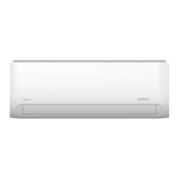
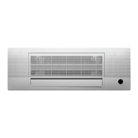
PARTS
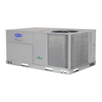
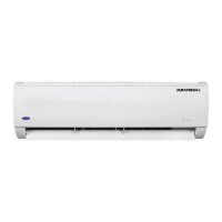
Fig. 2 — System Components
NOTE: Illustrations in this manual are for reference only. The actual shape of the indoor unit and parts may differ slightly.
1. Air Inlet (with air filter installed)
2. Air Flow Louver
3. Hanging Bracket
4. Display Panel
5. Drainage Pipe
6. Refrigerant Piping
7. Air Inlet
8. Air Outlet
9. Remote Controller
10. Outdoor Unit Power Cable (field supplied by installing contractor)
NOTES:
- If the outdoor unit is higher than the indoor unit, prevent rain from
flowing into the indoor unit along the connection pipe by making a
inverted trap in the connection pipe before it enters the wall to the
indoor unit. This ensures that rain drips from the connection pipe
before it enters the wall.
- Piping and the interconnecting wiring are field supplied.
- Figure 2 is a sketch. Different models may differ slightly.
The units listed in Table 3 are addressed in these installation instructions.
Table 3 — Indoor Units
NOTE: The installation must be performed in accordance with the
requirement of local and national standards. The installation
may differ slightly in some areas.
ʒ
ʓ
ʔ
ʕ
ʖ
ʗ
ʘ
ʘ
ʙ
Disconnect Switch (Factory Installed/Standard)
Outdoor unit power cable
Hanging bracket
DESCRIPTION BTUH V-PH-HZ ID MODEL NO.
CASSETTE
6
208/230-1-60
DLFSOAH09XAK
9
12
DLFSOAH18XAK
18