FCM/A5, FEV, FJM, FEM4, FHMA5, FMA4/5, FM(C,U)5, FS(A,M,U)4, FTMA5, F(V,X)M4, F5M4, REM4, WA(H,M,P,X) WB(G,H)L, WC(G,H)L: Service and Maintenance
Manufacturer reserves the right to change, at any time, specifications and designs without notice and without obligations.
12
Superdehumidify mode, the G signal is not present and the auxiliary
terminals are not energized. If the installation includes the use of this
operating mode, do not use these terminals to control accessories. See
Electronic Air Cleaner and Humidifier sections for further information.
ELECTRONIC AIR CLEANER CONNECTIONS—The AUX1 and
AUX2 terminals are not always energized during blower operation, as
described above. When using an electronic air cleaner with the FV4 fan
coil, use an Airflow Sensor or Airflow Verification switch. The airflow
sensor turns on the electronic air cleaner when the fan coil blower is
operating.
HUMIDIFIER/HUMIDISTAT CONNECTIONS—Easy Select Board
terminals HUM1 and HUM2 are provided for direct connection to the
low-voltage control of a humidifier through a standard humidistat. These
terminals are energized with 24VAC when G thermostat signal is
present. Alternately, the 24VAC signal may be sourced from the W and
C terminal block connections when electric heaters are used as primary
heating source. When using a Thermidistat™ Control, Zone Perfect
Plus, or Comfort Zone II, the 24VAC signal may be source directly from
the Thermidistat HUM terminal.
Dehumidify Mode
NOTE: Humidistat must open on humidity rise.
Latent capacities for systems using the FVM4 and FTM fan coils are
better than average systems. If increased latent capacity is an application
requirement, the field wiring terminal block provides connection
terminals for use of a standard humidistat. The FVM4 and FTM fan coils
will detect the humidistat contacts opening on increasing humidity and
reduce its airflow to approximately 80 percent of nominal cooling mode
airflow. This reduction will increase the system latent capacity until the
humidity falls to a level which causes the humidistat to close its contacts.
When the contacts close, airflow will return to 100 percent of the
selected cooling airflow. To activate this mode, remove jumper J1 and
wire in a standard humidistat. Carefully consult product airflow data for
cooling and dehumidification modes.
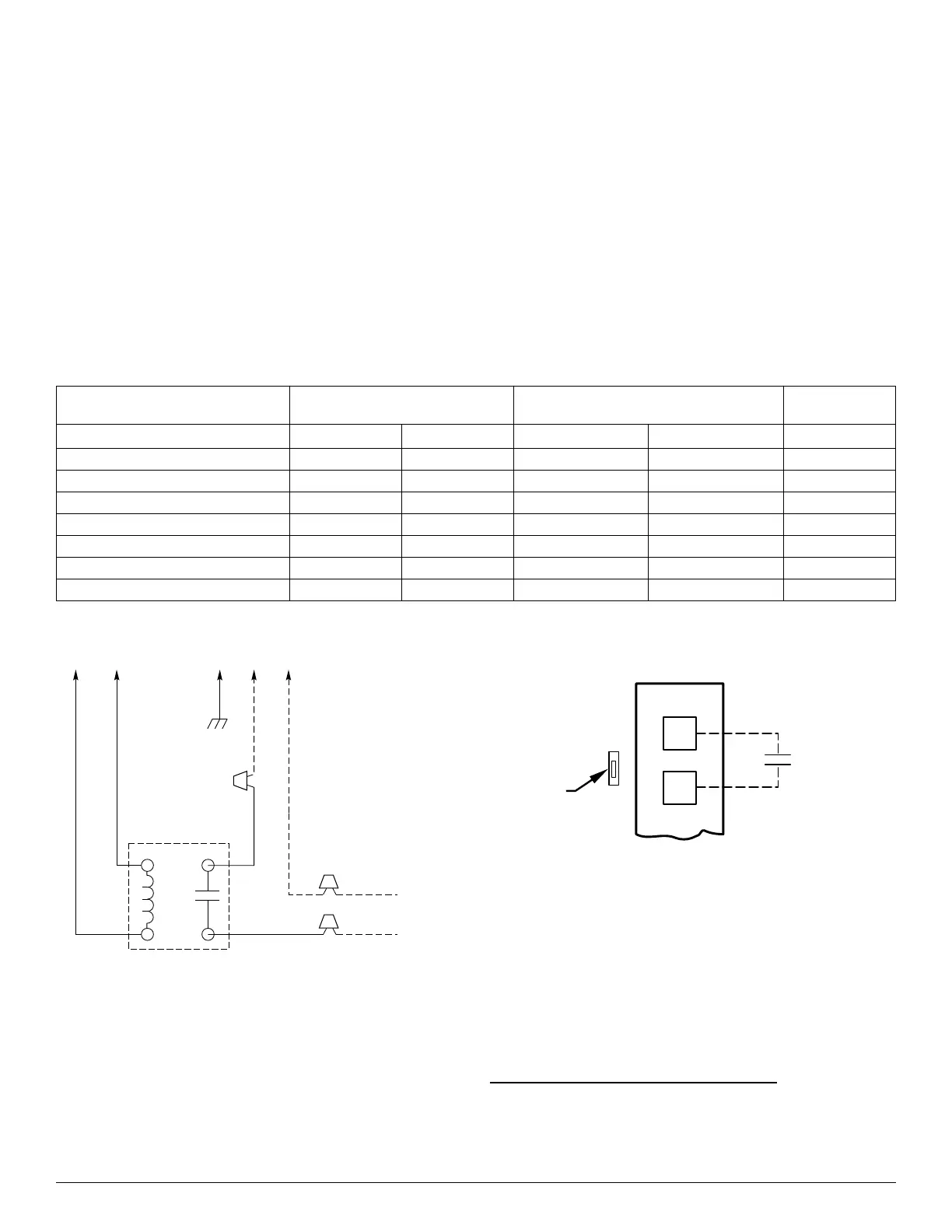
A98625
Fig. 9 – Relay Kit Wiring Schematic
A95316
Fig. 10 – Humidistat Wiring for De-Humidify Mode
FCM
Model FCM fan coil is designed to be installed with a communicating
user interface. The FCM fan coil will provide airflow at a rate
commanded by the User Interface. The nominal airflow/ton rate is 350
CFM/ton. The User Interface will modify the commanded airflow under
certain operating modes. Refer to the User Interface literature for further
system control details. This fan coil will not respond to commands from
a common thermostat except under certain emergency situations
explained in this document.
Electronically Commutated Motor ECM
An ECM motor is fed high voltage AC power through the 5-pin
connector. The AC power is then internally rectified to DC by a diode
module. After rectification, DC signal is electronically communicated
and fed in sequential order to 3 stator windings. The frequency of these
Table 6 – FVM4/FTM Motor Control Test Values (With 16-pin connector at motor unplugged)
Terminals
Jumpered
Volt Meter on 16-pin Harness Plug
Volt Meter on 12-pin
Easy Select Board Plug
Voltage
+ – + –
R to W1 Pin 2 Pin 1 Pin 7 Pin 9 24VAC
R to W2 Pin 13 Pin 1 Pin 4 Pin 9 24VAC
R to Y1 Pin 6 Pin 1 Pin 3 Pin 9 (-)12VDC
R to Y/Y2 Pin 14 Pin 1 Pin 2 Pin 9 (-)12VDC
R to G (LO) Pin 15 Pin 1 Pin 3 Pin 9 0VAC
R to G (MED) Pin 6 Pin 1 Pin 3 Pin 9 (-)12VDC
R to G (HI) Pin 14 Pin 1 Pin 2 Pin 9 (-)12VDC
24 VAC RELAY
FAN COIL
230 VAC OR
115 VAC BRANCH CKT
AUX1
(C)
AUX2
(G)
GND HOT NEUT
GRN
BLK
WHT
NO
COM
BLK
BLK
RED
RED
WHT
TO EAC
EASY SELECT
BOARD TERMINAL
BLOCK
D
H
J1
R
HUMIDISTAT
REMOVE
JUMPER