FCM/A5, FEV, FJM, FEM4, FHMA5, FMA4/5, FM(C,U)5, FS(A,M,U)4, FTMA5, F(V,X)M4, F5M4, REM4, WA(H,M,P,X) WB(G,H)L, WC(G,H)L: Service and Maintenance
Manufacturer reserves the right to change, at any time, specifications and designs without notice and without obligations.
19
A150463
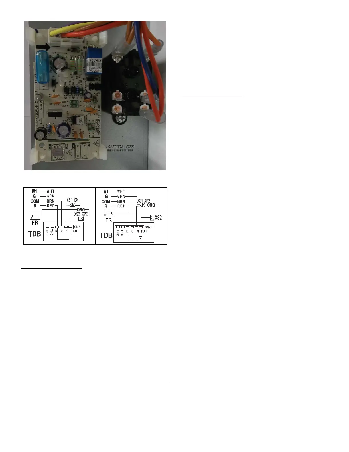
Fig. 15 – SMA4 Size 30 & 36 PCB
A180074
Fig. 16 – Time Delay Schematic
Electric Heater Service
Service can be completed with heater in place. Shut off power before
servicing.
Limit Switch
Refer to (Electric Heater Function and Troubleshooting on p23).
Sequencer
Early EHK2 heater kits included sequencers instead of relays. Refer to
(Electric Heater Function and Troubleshooting on p23).
Transformer
A 40VA transformer supplies 24V power for control circuit. Check for
208/230V on primary side of transformer. If present, check for 24V on
secondary side.
NOTE: Transformer is fused. Do not short circuit.
Fan Relay
Later EHK2 heater kits included relays instead of sequencers. Relay coil
is 24V. Check for proper control voltage. Replace relay if faulty.
Cleaning or Replacing Refrigerant Flow-Control Device
FMA4P, WAMA
The piston can be removed and cleaned if believed to be plugged. This
unit’s piston is unique and replacements are available from RCD.
The filter drier should be located on the liquid line at the indoor unit to
prevent particulate from plugging the piston.
FMA4X, WAXA, FMA5L, FMA5X
These fan coils use a TXV. The TXV’s are preset at the factory and do
not need adjustment for reliable operation. Reference the outdoor unit
instructions to properly charge the unit to the correct subcooling. For
optimal performance, adjust the TXV so that 6º F of superheat is
measured at the outdoor unit’s vapor service valve when the indoor
return air is 80º F DB/67º F WB and outdoor ambient is 82º F DB. To
increase superheat turn the TXV adjustment stem clockwise no more
than one rotation at a time. After an adjustment is made, wait until the
superheat temperature has been stable for 15 minutes before making
further adjustments.
Sequence of Operation
Condensing Unit
COOLING—When thermostat calls for cooling, the circuit between R
and G is complete and single-pole single-throw relay FR is energized.
The normally open contacts close causing blower to operate.
The circuit between R and Y is also complete. This completed circuit
causes contactor in outdoor unit to close which starts compressor and
outdoor fan. When thermostat is satisfied, its contacts open
de-energizing contactor and blower relay. This stops compressor and
outdoor fan motor. The indoor fan motor will stop after 90-100 seconds
on the FMA4P, and 30 or 90 seconds on the FMA4X, and FMA5L/X.
HEATING—When thermostat calls for heating and FAN switch is set
on AUTO, the circuit between R and W is complete. The heater
sequence SEQ is energized which closes contacts of relay. There will be
a time delay. This completed circuit energizes all heating elements HTR
and blower motor. When thermostat is satisfied, its contacts open
de-energizing heat relay. This de-energizes the sequencer. All heaters
should stop. The indoor fan motor will stop after 90-100 seconds on the
FMA4P, and 30 or 90 seconds on the FMA4X and FMA5L/X.
Heat Pump
COOLING—On a call for cooling, the thermostat makes circuits R-O,
R-Y, and R-G. Circuit R-O energizes reversing valve, switching it to
cooling position. Circuit R-Y energizes contactor starting outdoor fan
motor and compressor. Circuit R-G energizes indoor unit blower relay
starting indoor blower motor.
When thermostat is satisfied, its contacts open de-energizing contactor
reversing valve and blower relay. This stops compressor and outdoor fan
motor. The indoor fan motor will stop after 90-100 seconds on the
FMA4P, and 30 or 90 seconds on the FMA4X and FMA5L/X.
HEATING—On a call for heating, the thermostat makes circuits R-Y
and R-G. Circuit R-Y energizes contactor starting outdoor fan motor and
compressor. Circuit R-G energizes indoor blower relay starting blower
motor.
Should temperature continue to fall, R-W circuit is made through
second-stage room thermostat bulb. Circuit R-W energizes a sequencer
bringing on supplemental electric heat.
When thermostat is satisfied, its contacts open de-energizing contactor
and sequencer. All heaters should stop. The indoor fan motor will stop
after 90-100 seconds on the FMA4P, and 30 or 90 seconds on the
FMA4X.
FMA5L and FMA5X units are equipped with an R-454B refrigerant
dissipation system. This system comes with a leak detection sensor
located behind the slope coil. While a leak event is being detected by the
sensor, the EHK2 (heater kit) will be inoperable until the unit is no
longer in dissipation mode.