FCM/A5, FEV, FJM, FEM4, FHMA5, FMA4/5, FM(C,U)5, FS(A,M,U)4, FTMA5, F(V,X)M4, F5M4, REM4, WA(H,M,P,X) WB(G,H)L, WC(G,H)L: Service and Maintenance
Manufacturer reserves the right to change, at any time, specifications and designs without notice and without obligations.
18
Time Delay
FMA4X, FMA5X and WAXA have time delay built into the motor logic.
FMA4P, FMA5L and WAMA units with date codes prior to 1715V have
sequencers. FMA4P, FMA5L and WAMA units with date codes 1715V
or later have a time delay printed circuit board.
The Time Delay Printed Circuit Board (PCB) s a logic controlled time
delay activated by low-voltage control signal (G) from thermostat. The
PCB includes a normally open relay which closes to energize the blower
motor when the G terminal is energized. Then when the G terminal is
de-energized the relay energizing the blower motor remains closed for
90–100 seconds before opening.
NOTE: Aluminum coil models with PSC motor can be wired to
different OFF time delay. See installation instructions for wiring
diagram.
FMA5X units have time delay built into the motor logic. See the Motor
Speed Taps table in the installation instructions. FMA5L have the time
delay functionality integrated into the control board.
NOTE: The following sequence of operation is based on units installed
with PSC motor and Time Delay Printed Circuit Board (PCB), and all
FMA5L units. For units with ECM motor, the off-delay is programmed
into the motor. Follow Table 9 below, ECM Motor Speed Taps & the
corresponding blower OFF delays for each speed tap. For FMA5X units,
see the Motor Speed Taps table in the Installation Instructions.
Continuous Fan
Thermostat closes R to G. G energizes and completes circuit to indoor
blower motor. When G is de-energized, there is a 90-second blower
off-delay.
Cooling Mode
Thermostat energizes R to G, R to Y, and R to O (heat pump only). G
energizes and completes indoor blower motor. Y energizes outdoor unit
(O is energized for heat pump). When cooling call is satisfied, G is
de-energized, there is a 90-second blower off-delay.
Heat Pump Heating Mode
Thermostat energizes R to G and R to Y. G energizes and completes
circuit to indoor blower motor. When heating call is satisfied, G is
de-energized, there is a 90-second blower off-delay.
Heat Pump Heating with Auxiliary Electric Heat
Thermostat energizes R to G, R to Y, and R to W1. G energizes and
completes circuit to indoor blower motor. W1 energizes electric heat
relay(s) which completes circuit to heater element(s). When W1 is
de-energized, electric heat relay(s) open, turning off heater elements.
When G is de-energized there is a 90-second blower off-delay.
Electric Heat or Emergency Heat Mode
Thermostat closes R to W1. W1 energizes electric heat relay(s) which
completes circuit to heater element(s). Blower motor is energized
through normally closed contacts on fan relay. When W1 is
de-energized, electric heat relay(s) opens, there is no blower off-delay.
(units with ECM motor will have a blower off-delay based on motor
speed tap selection).
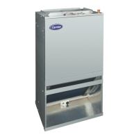
A150462
Fig. 14 – FMA4 Size 18 & 24 PCB
Table 9 – Speed Tap and Off -Delay Time (FMA4)
Speed
Tap
Off-Delay
Time
18 24 30 36
Tap 1 30 - - - -
Tap 2 90 Default - Default -
Tap 3 30 - - - -
Tap 4 90 - Default - Default
Tap 5 30 - - - -
Table 10 – FMA5X ECM Motor Speed Taps Delay Off Time Setting
Tap 18 24 30 36
Tap 1
30 30 30 30
Tap 2
30 30
30/90
*
*. Default setting
Where two numbers are shown, left represents Minor series 1 and right
represents Minor series 2.
A150455B
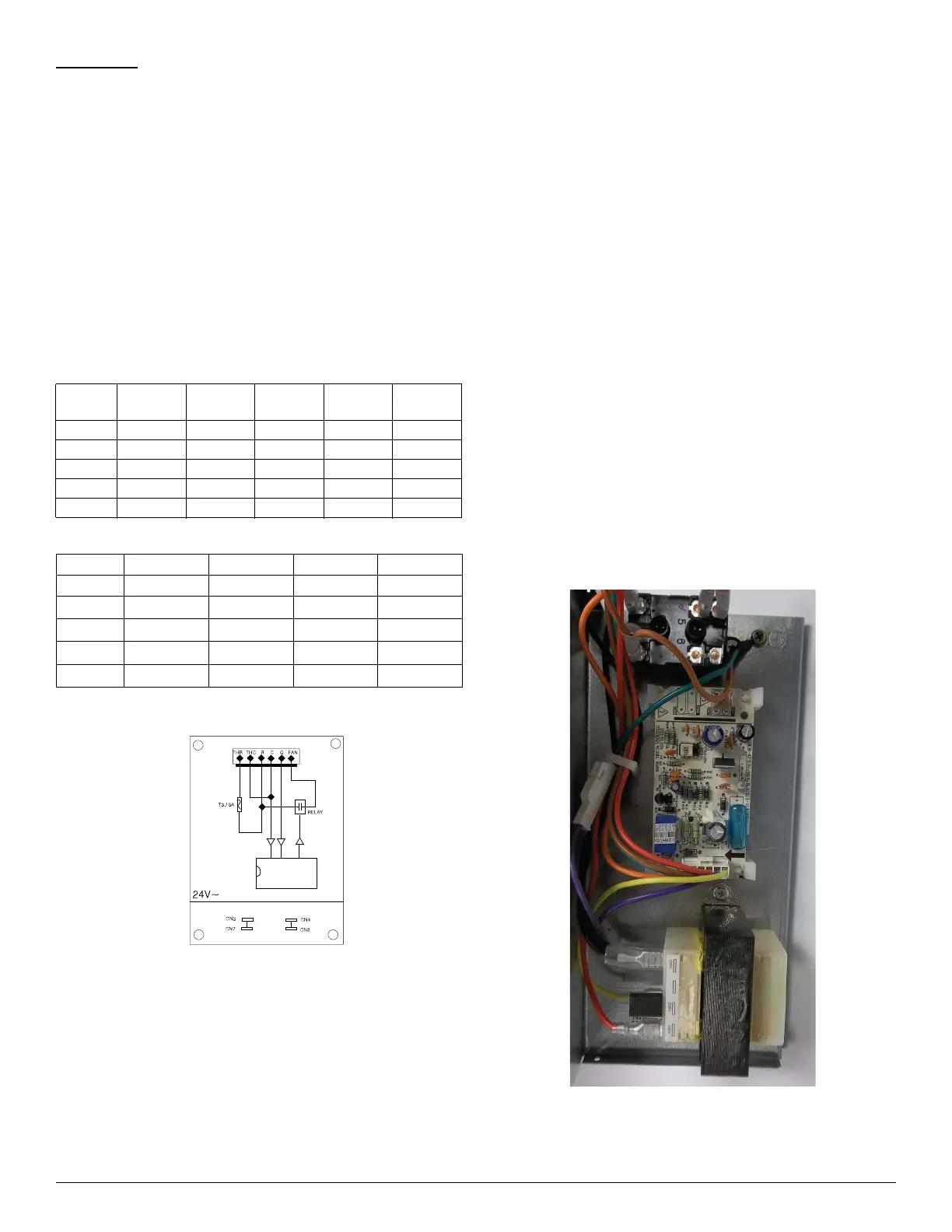
Fig. 1 – Time Delay PCB Schematic
30/90
Tap 3
90
*
90 90/30 90/30
Tap 4
90/0 90/0 90
90
*
Tap 5
90
90
*
90/0 90/0
Comments:
1. The THR and THC are connected to transformer output.
2. When the G has signal, the FAN will supply 24VAC power
to control fan relay.
3. Whe the G signal is gone, the FAN will stop 24 VAC output
after 90 seconds.
4. CN3, CN7 are dummy connection terminals.