FCM/A5, FEV, FJM, FEM4, FHMA5, FMA4/5, FM(C,U)5, FS(A,M,U)4, FTMA5, F(V,X)M4, F5M4, REM4, WA(H,M,P,X) WB(G,H)L, WC(G,H)L: Service and Maintenance
Manufacturer reserves the right to change, at any time, specifications and designs without notice and without obligations.
7
Electrical Connections
Twenty-one 0.110-in pin terminals are used to provide programming
selections for operating modes of ECM2.3/5.0. The selection modes are
listed below. For additional information, refer to Easy Select
Configuration Taps section.
• AUX Heat Range—(Violet Wire)
• AC/HP Size—(Blue Wire) Type—(Orange Wire)
• AC/HP CFM Adjust—(Black Wire)
• AC/HP Time Delay—(Grey Wire)
• Continuous Fan—(Yellow Wire)
Sequence of Operation (FTM, FVM)
Continuous Fan Mode
The thermostat closes circuit R to G. The unit delivers the airflow
selected for fan only operation.
Cooling Mode—Single Speed or Two-Speed High
Thermostat closes circuits R to G, R to Y/Y2 and R to O (heat pump
only). A circuit R to Y1 is required for two-speed high operation.
Airflow delivered the airflow selected by AC/HP SIZE selection and
CFM ADJUST selection.
Cooling Mode—Two-Speed Low
Thermostat closes R to G and R to Y1 and R to O (heat pump only). Unit
delivers two-speed low airflow for AC/HP SIZE and CFM ADJUST
selected.
Cooling + Dehumidify Mode
J1 jumper must be pulled from Easy Select Board. Control closes R to G,
R to Y/Y2, and R to O (heat pump only) and open R to DH.
Dehumidification is active when 24VAC is removed from DH terminal.
Unit delivers 20 percent less airflow.
SuperDehumidify Mode
This mode is only activated by the indoor control when control closes R
to Y/Y2, R to O (heat pump only) and opens R to DH and R to G. This
signals the fan coil to run at minimum airflow for maximum humidity
removal. The control will cycle the equipment 10 minutes on and 10
minutes off until satisfied.
NOTE: Super Dehumidification and Thermidistat functionality is not
available with certain thermostat models. Verify with the thermostat
manufacturer if this functionality is critical to the application.
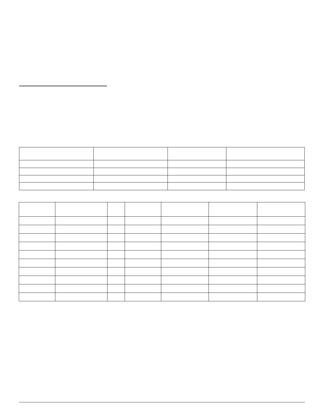
Table 1 – Motor and Modules
Model Size Motor Type Current Blower Motor P/N
Required Control Module
Replacement Kit Number
FVM4X2400 (Series B) ECM 5.0 1185246 1185326
FVM4X3600 (Series B) ECM 5.0 1185247 1185327
FVM4X4800 (Series B) ECM 5.0 1185248 1185328
FVM4X6000 (Series B) ECM 5.0 1185249 1185329
Table 2 – Motor and Modules – post-2023 (Mid and Deluxe Tier)
Configuration Fan Coil Model Family Size Motor Type Motor P/N
Motor Signal
Translator P/N
Control Module P/N
Singular FTMA4, FTMA5 24 ECM HD44RM600 HK43EJ001 HK61EA024
Modular FTMA4, FTMA5 36 ECM HD44RM600 HK43EJ002 HK61EA024
Modular FTMA4, FTMA5 48 ECM HD46RM600 HK43EJ003 HK61EA024
Modular FTMA4, FTMA5 60 ECM HD46RM600 HK43EJ004 HK61EA024
Singular FCMB4 24 ECM HD44RM600 N/A HK38EA061
Singular FCMB4 36 ECM HD44RM600 N/A HK38EA061
Singular FCMB4 48 ECM HD46RM600 N/A HK38EA061
Modular FCMB4 36 ECM HD44RM600 N/A HK38EA061
Modular FCMB4 48 ECM HD46RM600 N/A HK38EA061
Modular FCMB4 60 ECM HD46RM600 N/A HK38EA061