FCM/A5, FEV, FJM, FEM4, FHMA5, FMA4/5, FM(C,U)5, FS(A,M,U)4, FTMA5, F(V,X)M4, F5M4, REM4, WA(H,M,P,X) WB(G,H)L, WC(G,H)L: Service and Maintenance
Manufacturer reserves the right to change, at any time, specifications and designs without notice and without obligations.
8
A13029
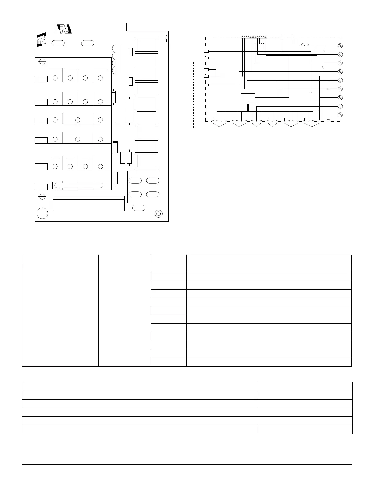
Fig. 7 – Easy Select Board
A96431
Fig. 8 – Easy Select Board Schematic
Heat Pump Heating Mode — Single Speed or Two-Speed High
Thermostat closes R to Y/Y2 and R to G. A circuit R to Y1 is required
for two-speed high operation. The unit delivers airflow selected by
AC/HP SIZE selection and CFM ADJUST selection. Selected delay
profile is active in this mode.
YYWWX
AUX/HEAT KW/CFM
AC/HP SIZE
AC/HP CFM ADJUST
ON/OFF DELAY
CONTINUOUS FAN
HEATER/MOTOR
AUX1 HUM1
AUX2
24VAC
HUM2
LO MED HI YEL
SYSTEM TYPE
SEC1
®
®
EASY SELECT
SEC2
J1
5 AMP.
MAX.
F1
D4
D5D2
D3
D1
R1
R2
HK61EA006
5
STI
J2
YEL
PL1
GRY
WHT
BLK
ORN
BLU
VIO
0-30
1075
0-20
875
0-10
725
0-5
625
036 030 024 018
AC HP-COMFORT HP-EFF
NOM LO HI
0
90
30
90
0
0
ENH
D
H
R
W
1
W
2
Y
1
Y/Y
2
G
O
C
1
AUX1
SYSTEM DIAGRAM
HEATER/MOTOR
12
11
10
9
8
7
6
5
4
3
2
1
SEC1 SEC2
5 AMP
J1
D
H
R
W
1
W
2
Y
1
Y/Y
2
G
O
C
J2
HUM1
AUX2
HUM2
DIODE
LOGIC
AUX HEAT
KW/CFM
AC/HP
SIZE
SYSTEM
TYPE
AC/HP CFM
ADJUST
ON/OFF
DELAY
CONTINUOUS
FAN
GRY
1
/
4
"
1
/
4
"
1
/
4
"
1
/
4
"
1
/
4
"
1
/
4
"
1
/
4
"
Table 3 – Connections and Connectors (FK4, FV4)
Type Connection Type Connector Pin No. Description
Heater Connection 12-Pin
Pin 1 Common to screw terminal G
Pin 2 Common to screw terminal Y/Y2 through diode D3
Pin 3 Common through Y1 through diode D2
Pin 4 Common to W2 screw terminal
Pin 5 Common to W2 screw terminal
Pin 6 Common to W1 screw terminal
Pin 7 Common to W1 screw terminal
Pin 8 R 24Vac
Pin 9 Common to transformer C
Pin 10 Common to transformer C
Pin 11 Common to transformer C
Pin 12 Common to DH screw terminal
Table 4 – Typical Operating Modes
Operating Mode Terminals Energized
Heat Pump Only Heating R, Y/Y2, G, DH
Heat Pump Only Heating + Super Comfort Heat Mode R, Y/Y2, DH
Heat Pump Heating + Auxiliary Heat (non-staged) R, Y/Y2, G, DH, W2
Cooling R, Y/Y2, G, DH, O
Cooling + Dehumidification R, Y/Y2, G, O