GH7T: Installation Instructions
Manufacturer reserves the right to change, at any time, specifications and designs without notice and without obligations.
6
A12258
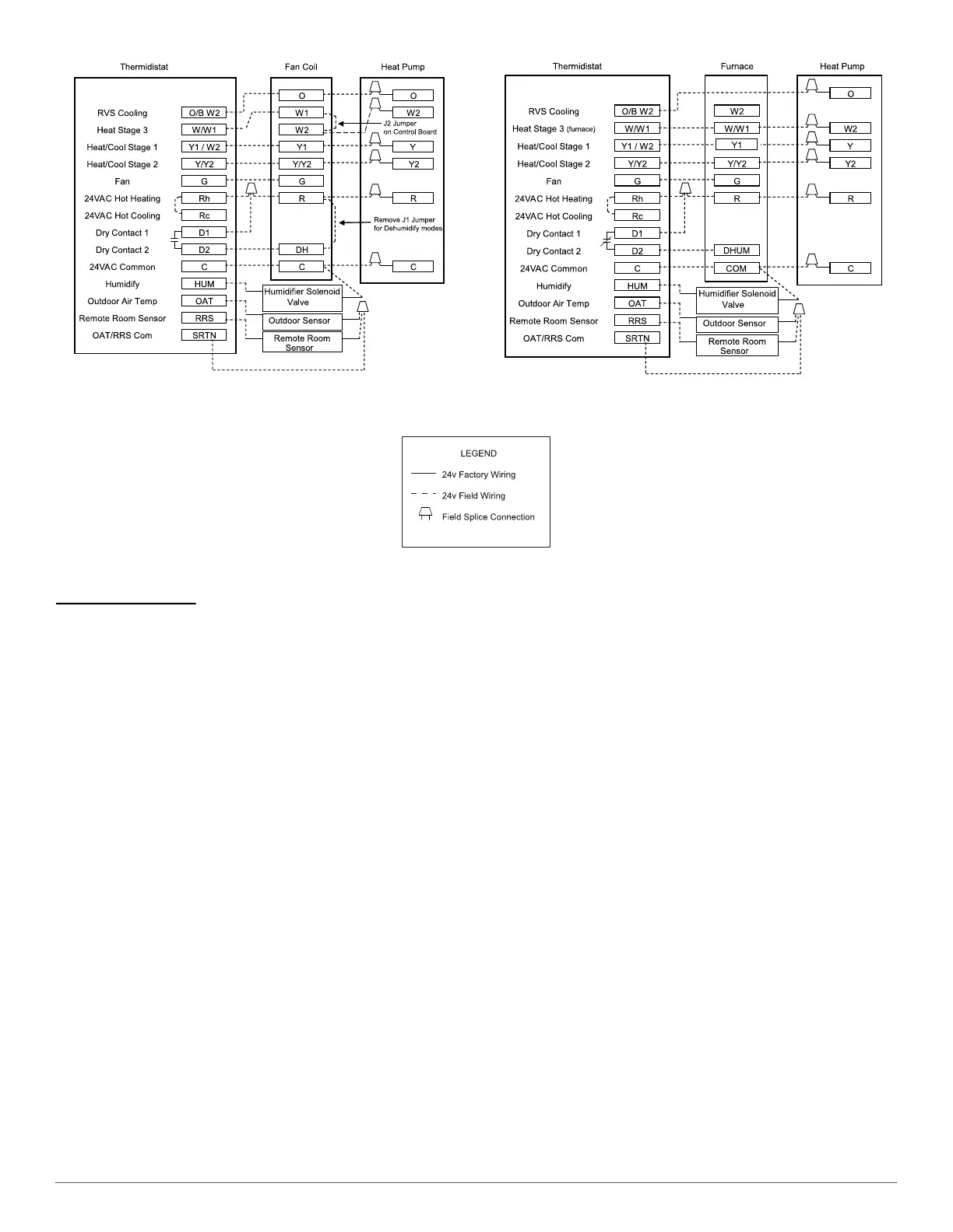
Fig. 9 – Thermidistat Wiring with Fan Coil
and 2-Stage Heat Pump
A12259
Fig. 10 – Thermidistat with Variable Speed Furnace
and 2--Stage Heat Pump
A09306
Final Wiring Check
IMPORTANT: Check factory wiring and field wire connections to
ensure terminations are secured properly. Check wire routing to ensure
wires are not in contact with tubing, sheet metal, etc.
Compressor Crankcase Heater
All sizes are equipped with a crankcase heater. Furnish power to heater a
minimum of 24 hours before starting unit. To furnish power to heater
only, set thermostat to OFF and close electrical disconnect to outdoor
unit.
A crankcase heater is required if refrigerant tubing is longer than 80 ft.
(24.4 m), or when outdoor unit is 20 ft. (6.1 m) below the indoor unit.
Refer to the Residential Piping and Long Line Guideline.
Install Electrical Accessories
Refer to the individual instructions packaged with kits or accessories
when installing.
Airflow Selections (ECM Furnaces)
The ECM Furnaces provide blower operation to match the capacities of
the compressor during high and low stage cooling operation. Tap
selections on the furnace control board enable the installing technician to
select the proper airflows for each stage of cooling. Below is a brief
summary of the furnace airflow configurations
1. The Y2 call for high stage cooling energizes the “Cool” tap on the
control board. The grey wire from cool tap is connected to tap 5 on
the motor. Refer to the furnace Product Data to find the
corresponding airflow. If the airflow setting for high cooling needs
to be switched from tap 5 to a different tap, jumper a connection
from the cool tap to the desired tap so that the Y2 signal is
communicated via the cool tap to the desired speed tap.
2. The Y1 call for low stage cooling energizes the “Fan” tap on the
control board. The red wire from the fan tap is connected to tap 1 on
the motor. Refer to the furnace Product Data to find the
corresponding airflow. If the airflow setting for low cooling needs
to be switched from tap 1 to a different tap, jumper a connection
from the Fan tap to the desired tap so that the Y1 signal is
communicated via the Fan tap to the desired speed tap. The Y1
setting will also govern the continuous fan airflow for the furnace.
Refer to the literature for the furnace for further details.
Airflow Selection for Variable Speed Furnaces
(non-communicating)
The variable speed furnaces provide blower operation to match the
capacities of the compressor during high and low stage cooling
operation. The furnace control board allows the installing technician to
select the proper airflows for each stage of cooling. Below is a summary
of required adjustments. See furnace installation instructions for more
details:
1. Turn SW1-5 ON for 400 CFM/ton airflow or OFF for 350 CFM/ton
airflow. Factory default is OFF.
2. The A/C DIP switch setting determines airflow during high stage
cooling operation. Select the A/C DIP switch setting corresponding
to the available airflow shown in the furnace Installation
Instructions that most closely matches the required airflow shown
in the air conditioning Product Data for HIGH speed.
3. The CF DIP switch setting determines airflow during low stage
cooling operation. Select the CF DIP switch setting corresponding
to the available airflow shown in the furnace installation
instructions that most closely matches the required airflow shown
in the air conditioning Product Data for LOW speed. If a higher or
lower continuous fan speed is desired, the continuous fan speed can
be changed using the fan switch on the thermostat. Refer to the
furnace Installation Instructions for details of how to use this
feature.

 Loading...


