T -295
4-8
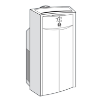
4.15 SERVICING THE LIQUID LINE SOLENOID
VALVE
The Liquid line solenoid valve (Figure 4-10) is very
similar to the heat valve. It requires no maintenance
unless a malfunction to the internal parts or coil occurs.
This may be caused by foreign material such as: dirt,
scale, or sludge in the refrigeration system, or improper
voltage to the coil.
There are only three possible valve malfunctions: coil
burnout, failure to open, or failure to close.
Coil burnout may be caused by the following:
1 Improper voltage.
2 Continuous over-voltage, more than 10% or under-
voltage of more than 15%.
3 Incomplete magnet circuit due to the omission of the
coil hosing or plunger.
4 Mechanical interface with movement of plunger
which may be caused by a deformed enclosing tube.
Failure to open may be caused by the following:
1 Coilburnedoutor anopencircuit to coilconnections.
2 Improper voltage.
3 Defective plunger or deformed valve body assembly.
Failure to close may be caused by the following:
1 Defective plunger or deformed valve body assembly.
2 Foreign material in the valve.
4.15.1 Coil Replacement
a. It is not necessary to remove the refrigerant charge
from the system.
b. .Place main battery disconnect switch in OFF posi-
tion and lock.
c. Disconnect wire leads to coil.
d. Remove coil retaining clip and nameplate.
e. Lift burned-out coil from enclosing tube and replace.
f. Connect wire leads and test operation
4.15.2 Internal Part Replacement
a. Placemainbatterydisconnect switchin OFFposition
and lock.
b. Perform a low side pump down. Refer to paragraph
4.5.1.
c. Slowly loosen enclosing tube assembly to bleed any
remaining pressure from the valve. Disassemble
valve and replace defective parts.
d. Assemble valve and leak check.
e. Evacuate low side and re--open system.
1
2
3
4
5
6
7
8
1. Snap Cap
2. Coil Assembly
3. Enclosing T ube
Assembly
4. Plunger Assembly
5. Gasket
6. Piston Assembly
7. Body
8. Bracket Adapter
Figure 4-10. Liquid Line Solenoid Valve
4.15.3.Replace Entire Valve
a. Perform a low side pump down, remove coil and
plunger assembly and un--braze valve from lines.
b. Remove valve assembly from bracket.
c. Disconnect wire leads to coil.
d. Disassemblenew valve, to protect internal parts, and
solder to lines.
e. Assemble and leak check valve.
f. Evacuate low side and re--open system.
g. Connect wire leads and test operation.
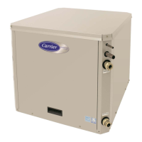
4.16 CONDENSER FAN/MOTOR ASSEMBLY
4.16.1 Removal
a. Placemainbatterydisconnect switchin OFFposition
and lock.
b. Unlatch m otor draw latches. See Figure 4-11.
c. Disconnect motor wire harness and lift m otor out of
unit.
4
1
2
3
4
5
1. Motor Support
2. Draw Latch
3. Fan/Motor Assembly
4. Motor
5. Brush
Figure 4-11. Condenser Fan/Motor Assembly