T -295
4-12
0.030 inch (0.41 to0.76 mm).Ifrequired, removethe
eight armature spacer nuts and spacer. Add orremove
shims to adjust gap. Reinstall spacer nuts and tighten
to 7--8 ft/lbs(1.0 to 1,1 mkg).
h.Reconnect wiring and test clutch operation.
4.20.3 Compressor Oil Level
To check, and if required correct, the compressor oil
level do the following:
a. Operate the coach for at least one--half hour at fast
idle speed, with the temperature controls at the cool-
est setting, andthe compressorfully loaded. It maybe
necessary to pre--heat the coach and/or operate the
system in thereheat modeto keep the compressorful-
ly loaded throughout this procedure
b. Ensure the system is fully char ged (refer to paragraph
4.8.1) and the compressor crankcase is warm to the
touch after fifteen minutes of operation.
c. Shut off the system and immediately record the oil
level in t he compressor sight glass. See Figure 4-17.
If the compressor is not level, an average between the
sight glass levels will have to be made to determine
level.
d. The properoil level is between the marks on thecom-
pressor crankcase (05G compressors) or between 1/4
and1/2 ofthesightglass(05Kcompressors). Referto
Figure 4-17. If the oil level is correct, release the
coach into service. If the level is above the required
amount, proceed to step e.. If the level is below the
required amount proceed to step f.
e. To remove oil and bring the level to the proper
amount, do the following:
1. Pump down the compressor until only a slight posi-
tive pressure remains in the crankcase. Refer topara-
graph 4.5.3.
2. Shut off t he coachengine and ensure thecompressor
discharge and suction service valves are frontseated.
Reclaim theremaining refrigerantin thecompressor
crankcase.
3. Drain or pump out compressor oil until the level is
brought to the minimum for this compressor.
4. Evacuate the compressor to 500 microns. Backseat
the compressorservicevalves and repeat theoillevel
check procedure.
f. To addoil tothecompressorcrankcase,do thefollow-
ing:
1. With the system off, connecta m anifold gauge set to
the compressor suction and discharge service valves
(SeeFigure 4-5) andreclaim therefrigerant to below
atmospheric pressure. Shut off the reclaimer and
verify the pressuredoes not rise. Ifthe pressure rises,
continue reclaiming until the pressure remains be-
low atmospheric.
2. Add oil tocompressor crankcase slowly, throughthe
oil fill plug opening (see Figure 4-17) to bring level
to mid range of allowed l evels.
3. Evacuate compressor to 500 microns. Backseat
compressor suction and discharge valves, start sys-
tem and recheck oil level.
4. Remove manifold gauge set.
1
2
3
4
5
6
7
8
9
10
11
12
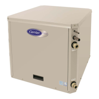
05K - GR45
05G - GR60
1
2
3
5
7
8
9
11
12
1. Electric Unloader
Valve
2. Suction Service
Valve Charging Port
3. Suction Service
Valve
4. Clutch
5. OilFillPlug
6. Bottom Plate
7. Oil Drain Plug
8. Oil Level Sight Glass
9. Oil Pump
10. O-ring
11 .Discharge Service
Valve
12 .Service Port
Figure 4-17. Compressors
4.20.4 Checking Unloader Operation
To check unloader operation do the following:
a. Install a manifold gauge set as shown in Figure 4-6.
Ensure both manifold valves are frontseated and cen-
ter connection is tight on blank fitting.
b. Midseat compressor suction service valve.
c. At thebus roof,disconnect thesuctionpressuretrans-
ducer (
8, Figure 1-6). This will force the controller to
energize the unloader(s).
d. Start t he bus and run in cooling lower set point if re-
quiredtoensuresystemremainsinfullspeedcooling.
e. Locatethe unloaderconnector at the compressor.Ob-
serve manifold suction gauge while unplugging the