5
INSTALLING INFINITY ZONE CONTROL
ELECTRICAL SHOCK HAZARD
Failure to follow this warning could result in personal injury
or death.
Before installing Infinity Zone Control, turn off all power to
equipment. There may be more than one power source to
disconnect.
!
WARNING
1. Turn off all power to equipment.
2. If an existing User Interface or control is being replaced:
a. Remove existing control from wall.
b. Disconnect wires from existing control.
c. Discard or recycle old control.
NOTE: Mercury is a hazardous waste, if existing control contains
any mercury, it MUST be disposed of properly. The User Interface
does not contain mercury.
3. Select Infinity Zone Control mounting plastic (recess mount
or surface mount and decorative backplate if desired).
4. Route wires through large hole in mounting plastic. Level
rear plastic against wall (for aesthetic value only -- Infinity
Zone Control need not be level to operate properly) and
mark wall through two mounting holes.
5. Drill two 3/16” (4.8 mm) mounting holes in wall where
mark ed.
6. Secure mounting plastic to wall using two screws and an-
chors provided.
7. Adjust length and routing of each wire to reach each wire
entry on the connector backplate. Strip 1/4” (6.4 mm) of in-
sulation from each wire.
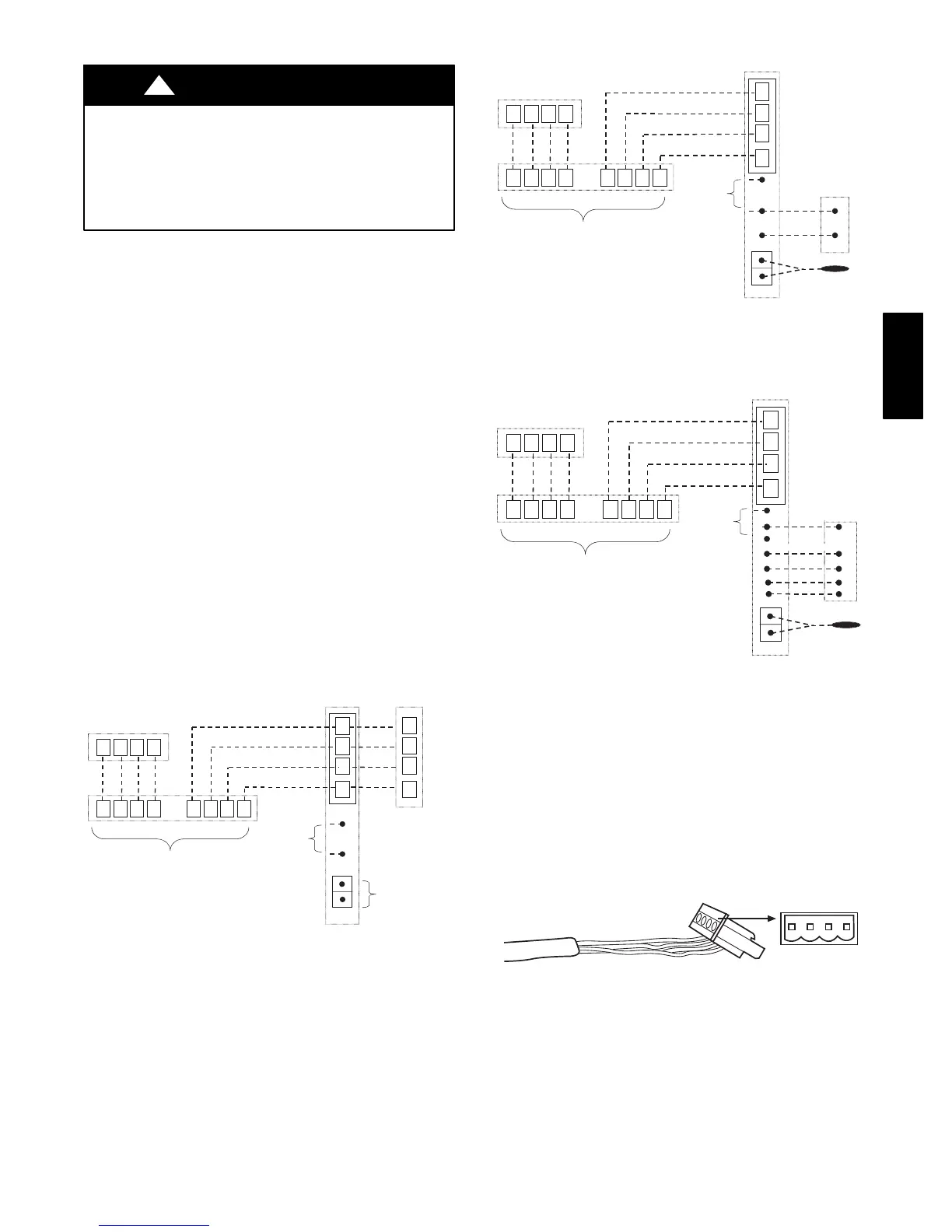
8. Match and connect thermostat wires to proper terminals on
User Interface backplate. See wiring diagram Fig. 11, 12,
and 13.
A
B
C
D
Zone Control
User Interface &
Smart Sensor(s)
Green
Yellow
White
Red
OAT
HUM
COM
24V
Humidifier
Connection
A
B
C
D
OAT
Sensor
(Optional)
A B C D A B C D
Damper
Control
module
A B C D
Indoor
Unit
Communicating
AC or HP
A04018
Fig. 11 -- Communicating Indoor Unit w/2--Stage Puronr
Refrigerant Communicating Outdoor Unit
A
B
C
D
Zone Control
User Interface &
Smart Sensor(s)
Green
Yellow
White
Red
OAT
HUM
COM
24V
Humidifier
Connection
OAT
Sensor
A B C D A B C D
Damper
Control
module
A B C D
Indoor
Unit
C
Y
1-Stage AC.
Y/Y2
A04019
Fig. 12 -- Connection Diagram for Furnace or FE Fan Coil
with Non--Communicating 1--Stage AC
A
B
C
D
Zone Control
User Interface &
Smart Sensor(s)
Green
Yellow
White
Red
A B C D A B C D
Damper
Control
module
A B C D
Variable-Speed
Fan Coil
1-Spd. HP
HUM
C
Y
W2
Y
O
C
R
O
R
W
OAT
OAT
Sensor
Humidifier
Connection
G
A07149
Fig. 13 -- Connection Diagram for FE Fan Coil with
Non-- Communicating 1--stage HP
A — Green = Data A
B — Yellow = Data B
C — White = 24VAC (Com)
D — Red = 24VAC (Hot)
NOTE: It is not mandatory that the above color code be used, but
each ABCD connection in the system MUST be wired consistently.
A separate ABCD Connector comes inside packaging and should
be used when connecting to furnace (or fan coil). Ensure connector
is inserted properly into circuit board. (See Fig. 14.)
ABCD
A03193
Fig. 14 -- Wire ABCD Connector
CCUIZ01 -- B