25TPB7: Installation Instructions
Manufacturer reserves the right to change, at any time, specifications and designs without notice and without obligations.
11
Troubleshooting
If the compressor fails to operate with a cooling call, the table below
(Resistance table) can be used to verify if there is any damage to the
compressor windings causing system malfunction.
Major Components
2-Stage Compressor
The 2-stage compressor contains motor windings that provide 2-pole
(3500 RPM) operation.
Compressor Internal Relief
The compressor is protected by an internal pressure relief (IPR) which
relieves discharge gas into compressor shell when differential between
suction and discharge pressures exceeds and 550 - 625 psi. The
compressor is also protected by an internal overload attached to motor
windings.
Compressor Control Contactor
The contactor has a 24 volt coil and is controlled by Y1 input from the
thermostat
Low Pressure Switch
Low pressure switch is provided in line with the Y1 signal to the
contactor for protection.
Care and Maintenance
For continuing high performance and to minimize possible equipment
failure, periodic maintenance must be performed on this equipment.
Frequency of maintenance may vary depending upon geographic areas,
such as coastal applications. See Users Manual for information.
Training
My Learning Center is your central location for professional residential HVAC training resources that help strengthen careers and businesses. We
believe in providing high quality learning experiences both online and in the classroom.
Access My Learning Center with your HVACpartners credentials at www.mlctraining.com. Please contact us a mylearning@carrier.com with
questions.
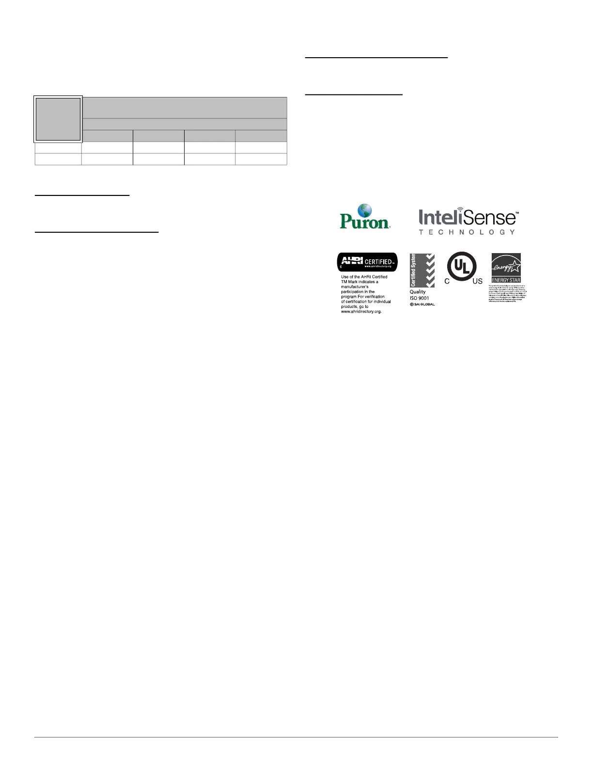
Table 3 – Winding Resistance
Winding
Winding resistance at 70°F +/- 20°F
(21.11°C +/- 11.11°C)
Unit Size
024 036 048 060
Start (S-C) 1.652 1.587 1.299 1.203
Run (R-C) 1.065 0.751 0.477 0.383