25TPB7: Installation Instructions
Manufacturer reserves the right to change, at any time, specifications and designs without notice and without obligations.
6
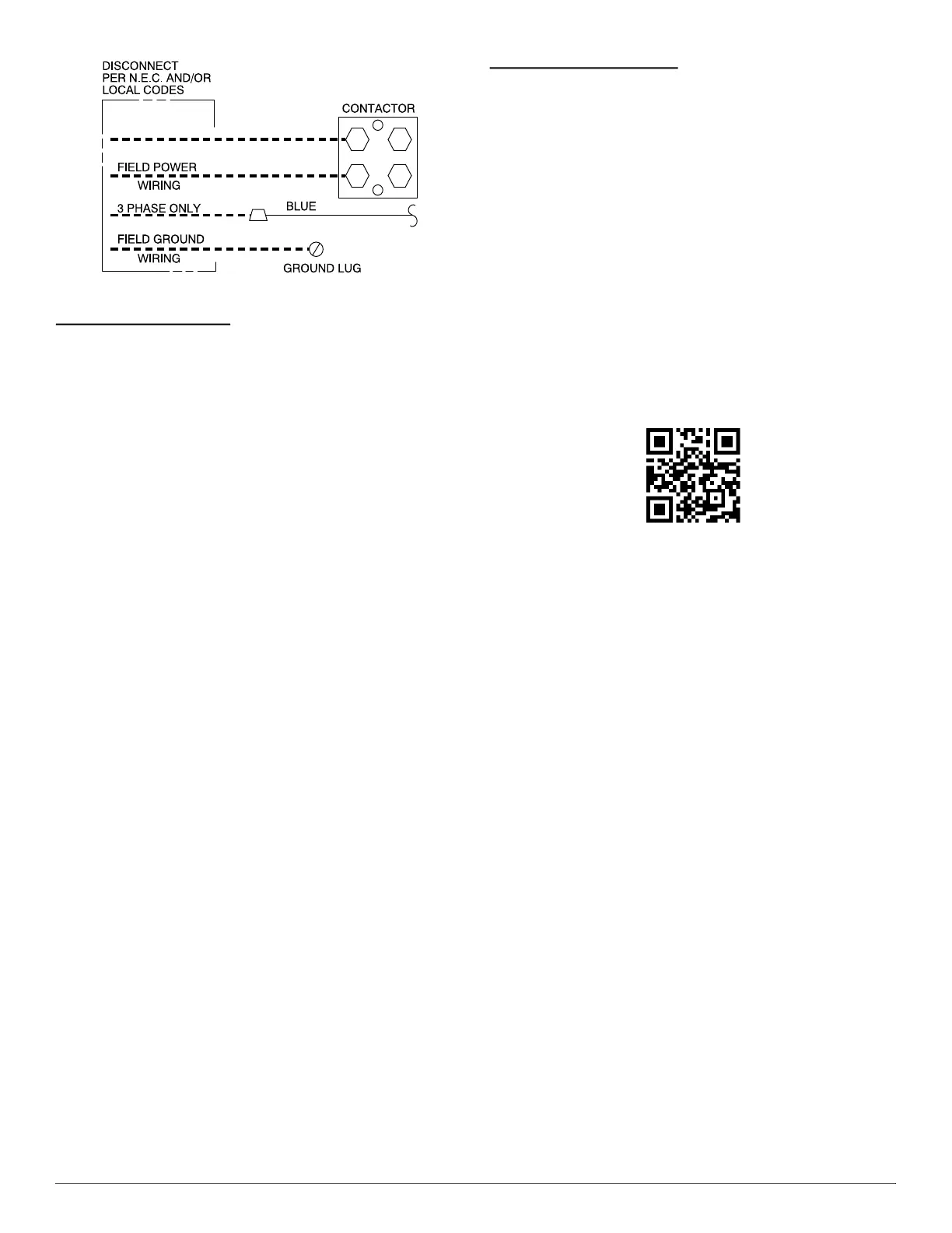
A94025
Fig. 8 – Line Connections
Connect Control Wiring
Route 24v control wires through control wiring grommet and connect
leads to control wiring. See Thermostat Installation Instructions for
wiring specific unit combinations. (See Fig. 9 and Fig. 10.)
All low voltage wiring, including those from the 2-Stage HP, should be
connected in the low voltage side of the panel.
Use No. 18 AWG color-coded, insulated (35°C minimum) wire. If
thermostat is located more than 100 ft (30 m) from unit, as measured
along the control voltage wires, use No. 16 AWG color-coded wire to
avoid excessive voltage drop.
All wiring must be NEC Class 2 and must be separated from incoming
power leads.
Use furnace transformer, fan coil transformer, or accessory transformer
for control power, 24v/40va minimum.
NOTE: Use of available 24v accessories may exceed the minimum 40va
power requirement. Determine total transformer loading and increase
the transformer capacity or split the load with an accessory transformer
as required.
InteliSense™ Technology
This unit is InteliSense™ capable when used with an Ecobee for Carrier
smart thermostat with InteliSense™ technology.
InteliSense™ technology allows for the collection of performance data
to be sent to the cloud. Utilizing Carrier’s digital tools, dealers can gather
system settings and equipment data, with homeowner opt-in, to provide
quicker and more efficient service. The unit comes with the following
sensors installed on the control board:
• Liquid Service Valve Pressure (LSVP)
• Liquid Service Valve Temperature (LSVT)
• Outside Air Temperature (OAT)
• Vapor Service Valve Pressure (VSVP)
• Vapor Service Valve Temperature (VSVT)
The amber LED is illuminated solid when there is power to the product.
The green LED is illuminated solid when there is communication
between the control board and the InteliSense™-enabled thermostat.
For more information, refer to the thermostat advanced installation and
configuration instructions found at:
Carrier.HVACPartners.com/InteliSense InteliSense™
Or, by scanning this QR Code:
NOTE: A new thermostat will show up in connected portal 24 hours
after field installation so field guages are needed for install.
NOTE: The outdoor temperature sensor does not show up on this new
thermostat display so it should not be used for troubleshooting or
charging.
NOTE: HP units with InteliSense™ technology do not come with
factory installed high pressure switch. Only loss of charge pressure
switch is factory installed.