11
12
34
A07216
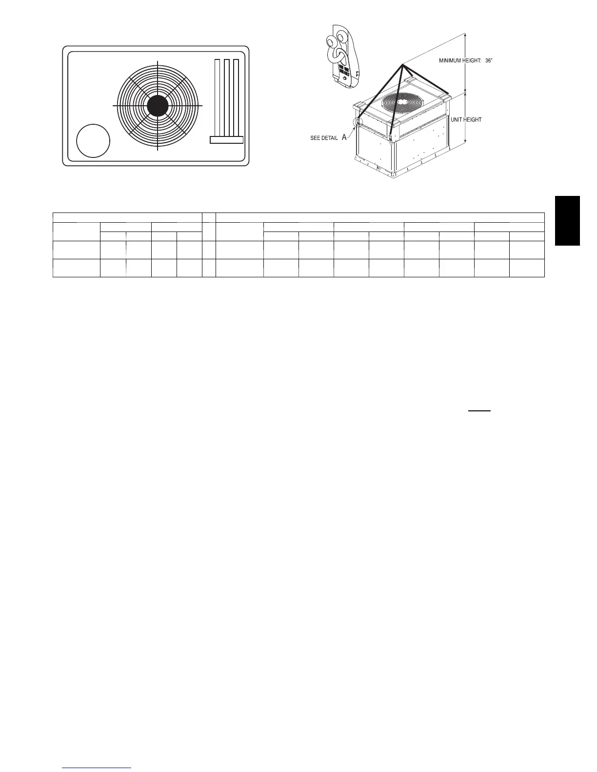
DETAIL A
(914 mm)
A08005
RIGGING WEIGHTS (SMALL CABINET) RIGGING WEIGHTS (LARGE CABINET)
Unit
024 030
Unit
036* 042* 048* 060*
lb kg lb kg lb kg lb kg lb kg lb kg
Shippi ng
Weight
354 171 364 165
Shippi ng
Weight
419 190 464 210 484 220 514 233
Rigging
Weight
317 144 327 148
Rigging
Weight
382 173 427 164 447 203 477 216
*For 460 volt units add 14 lb (6.4 kg) to the weight.
NOTE: See dimensional drawing for corner weight distribution. Corner weights shown on drawing are based on unit---only weights and do not include pack-
aging.
SELECTION PROCEDURE (WITH EXAMPLE)
1. Determine cooling and heating requirements at
design conditions:
Given:
Required Cooling Capacity (TC) 34,500 Btuh..........
Sensible Heat Capacity (SHC) 26,000 Btuh............
Required Heating Capacity 60,000 Btuh...............
Condenser Entering Air Temperature 95°F(35°C).......
Indoor-- Air Temperature 80°F(27°C) edb 67°F(19°C) ewb
Evaporator Air Quantity 1200 CFM..................
External Static Pressure 0.200 IN.W.C.................
Electrical Characteristics 208--1--60...................
2. Select unit based on required cooling capacity.
Enter Net Cooling Capacities table at condenser entering
temperature of 95°F(35°C). Unit 036 at 1200 cfm and 67°F
(19°C) ewb (entering wet bulb) will provide a total capacity of
36,000 Btuh and a SHC of 27,400 Btuh. Calculate SHC correction,
if required, using Note 4 under Cooling Capacities tables.
3. Select heating capacity of unit to provide design
condition requirement.
In the Heating Capacities and Efficiencies table, note that the 036
size unit will deliver 34,800 BTUH at the ARI high temp rating
point. To achieve 60,000 BTUH, accessory electric heat will be
required. Use the Balance Point Worksheet to plot the load line
with the unit capacity. The difference between the load line and
unit capacity at the design heating temperature is the amount of
electric heat that will be required.
4. Determine fan speed and power requirements at
design conditions.
Before entering the air delivery tables, calculate the total static
pressure required. From the given example, the Wet Coil Pressure
Drop T able, and the Filter Pressure Drop Table:
External Static Pressure 0.200 IN. W.C.
Filter 0.130 IN. W.C.
Wet Coil Pressure Drop 0.18
IN. W.C.
Total Static Pressure 0.51 IN. W.C.
Enter the table for Dry Coil Air Delivery— At 0.50 IN. W.C.
ESP (external static pressure) and MED--LOW speed the motor
delivers 1140 cfm. To achieve 1200 cfm, a higher speed tap is
required.
5. Select unit that corresponds to power source
available.
The Electrical Data Table shows that the unit is designed to operate
at 208/230-- 1--60.
50VT