PF4MNX: Installation Instructions
Manufacturer reserves the right to change, at any time, specifications and designs without notice and without obligations.
5
A00071A
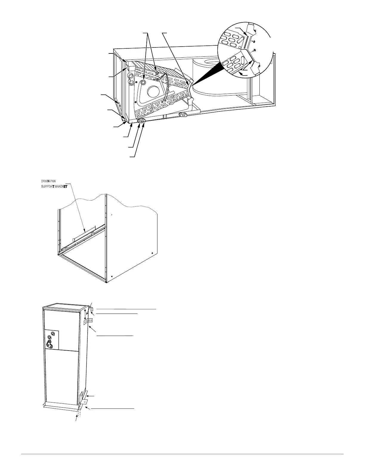
Fig. 6 – Conversion for Horizontal Right Applications - A-Coil
A07571
Fig. 7 – Drain Pan Support Bracket
A07567
Fig. 8 – Mobile Home or Manufactured Housing Applications
Air Ducts
Connect supply-air duct over the outside of ¾" (19 mm) flanges
provided on supply-air opening. Secure duct to flange, using proper
fasteners for type of duct used, and seal duct-to-unit joint. If return-air
flanges are required, install factory-authorized accessory kit.
Use flexible connectors between ductwork and unit to prevent
transmission of vibration. When electric heater is installed, use
heat-resistant material for flexible connector between ductwork and unit
at discharge connection. Ductwork passing through unconditioned space
must be insulated and covered with vapor barrier.
Units equipped with 20-30kW electric heaters require a 1" (25 mm)
clearance to combustible materials for the first 36" (914 mm) of supply
duct. All 18,000 BTU units equipped with 8 or 10 kW electric heaters
require a 1" (25.4 mm) clearance to combustible materials for the first
12" of supply duct.
Ductwork Acoustical Treatment
Metal duct systems that do not have a 90 degree elbow and 10 feet of
main duct before first branch takeoff may require internal acoustical
insulation lining. As an alternative, fibrous ductwork may be used if
constructed and installed in accordance with the latest edition of
SMACNA construction standard on fibrous glass ducts. Both acoustical
lining and fibrous ductwork shall comply with National Fire Protection
Association as tested by UL Standard 181 for Class 1 air ducts.
Electrical Connections
Units from the factory protect the low voltage circuit with a 3A
automotive type fuse in-line on the wire harness and Does Not contain a
circuit board. Motor speeds and time delay function are built into the
motor. See (Minimum CFM and Motor Speed Selection on p7) for
clarification.
When a factory-approved accessory control package has been installed,
check all factory wiring per unit wiring diagram and inspect factory
wiring connections to be sure none were loosened during transit or
installation. If a different control package is required, see unit rating
plate.
Before proceeding with electrical connections, make certain that supply
voltage, frequency, phase, and ampacity are as specified on the unit
rating plate. See unit wiring label for proper field high- and low-voltage
wiring. Make all electrical connections in accordance with the NEC and any local codes or ordinances that may apply. Use copper wire only.
COIL
SUPPORT
RAIL
COIL
BRACKET
DRAIN PAN
SUPPORT
BRACKET
COIL
SUPPORT
RAIL
COIL
BRACKET
HORIZONTAL
DRAIN PAN
PRIMARY DRAIN
HORIZONTAL RIGHT
SECONDARY DRAIN
HORIZONTAL RIGHT
REFRIGERANT
CONNECTIONS
AIR SEAL
ASSEMBLY
A
B
C
HORIZONTAL
RIGHT
APPLICATION
DOWN FLOW
BASE KIT (KFACB)
UNIT AGAINST WALL
.125" (3mm)
MOUNTING BRACKET
(TYPICAL BOTH SIDES)
SECURE FAN COIL TO STRUCTURE
UNIT AWAY FROM WALL
PIPE STRAP
(TYPICAL BOTH SIDES)
OR
SECURE UNIT TO FLOOR
ANGLE BRACKET OR PIPE STRAP
4” (102mm) MAX
4” (102mm) MAX