PF4MNX: Installation Instructions
Manufacturer reserves the right to change, at any time, specifications and designs without notice and without obligations.
8
A11048
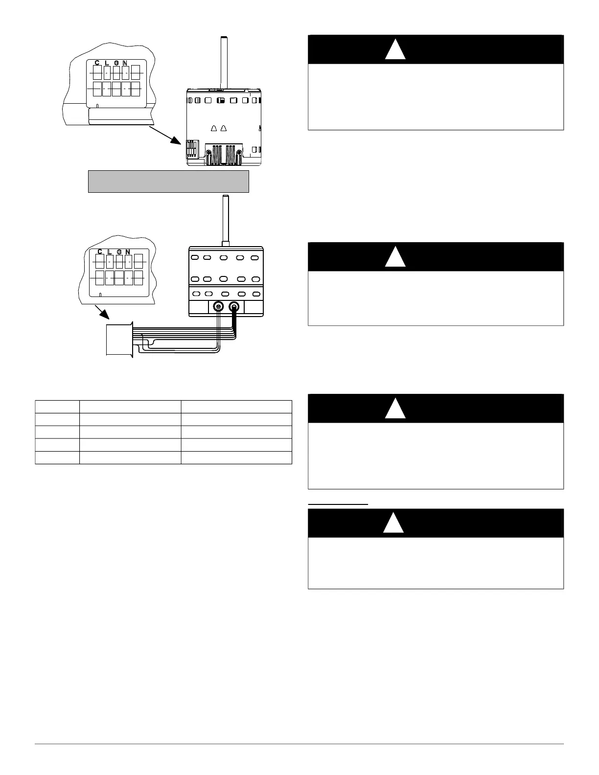
Fig. 14 – Motor Speed Selection
† electric heat airflow is same CFM as Tap 3, except 0 sec off delay
‡ high static applications, see airflow tables for max airflow
To change motor speeds disconnect the BLUE fan lead from motor
connector terminal #2 (factory default position) and move to desired
speed-tap; 1, 2, 3, or 5.
Speed-taps 1, 2, and 3 have a 90 second blower off time delay
pre-programmed into the motor. Speed-tap 4 is used for electric heat
only (with 0 second blower time delay) and the WHITE wire should
remain on tap 4. Speed-tap 5 is used for high static applications, but has
a 0 second blower time delay pre-programmed into the motor. See
Airflow Performance tables for actual CFM. Se Fig. 14 for motor speed
selection location.
NOTE: In low static applications, lower motor speed tap should be used
to reduce possibility of water being blown off coil.
Refrigerant Tubing Connection and
Evacuation
Use accessory tubing package or field-supplied tubing of refrigerant
grade. Suction tube must be insulated. Do not use damaged, dirty, or
contaminated tubing because it may plug refrigerant flow-control
device. ALWAYS evacuate the coil and field-supplied tubing to 500
microns before opening outdoor unit service valves.
Units have sweat suction and liquid tube connections. Make suction tube
connection first.
1. Cut tubing to correct length.
2. Insert tube into sweat connection on unit until it bottoms.
3. Braze connection using silver bearing or non-silver bearing brazing
materials. Do not use solder (materials which melt below 800° F /
427° C). Consult local code requirements.
4. Evacuate coil and tubing system to 500 microns using a deep
vacuum method.
Refrigerant Flow-Control Device
The 018-060 size units come equipped with a R-410A refrigerant
mechanical TXV. When tightening nuts on a TXV, do not exceed
20 ft-lbs.
Always use outdoor units designed to match indoor fan coil applications.
Disassembly
NOTE: For Item #1 (Fig. 15): Use an adjustable wrench with a backup
adjustable wrench to loosen the brass nut (TXV outlet). Then use both
wrenches to loosen Item # 2 (TXV inlet).
1. Use an adjustable wrench with a backup adjustable wrench to
loosen Item # 3 (TXV equalizer line).
2. For Item #4 - Cut the wire tie and remove the black insulation.
Remove the band from around the TXV bulb.
3. Cut the wire tie that holds the TXV equalizer line and bulb from the
aluminum vapor header tube.
4. Remove 2 screws from the TXV bracket. Remove the TXV from
the coil unit.
Table 1 – Fan Speed Selection
Tap 1
Low 90 sec off delay
Tap 2
Medium 90 sec off delay
Tap 3
High 90 sec off delay
Tap 4
Electric heat † 0 sec off delay
Tap 5
Max ‡ 0 sec off delay
1 2 3 4 5
Speed Taps may be located on motor,
or on plug close to motor.
CLGN
1 2 3 4 5
CAUTION
!
PRODUCT DAMAGE HAZARD
Failure to follow this caution may result in product or property damage.
A brazing shield MUST be used when tubing sets are being brazed to
the unit connections to prevent damage to the unit surface and
condensate pan fitting caps.
CAUTION
!
PRODUCT DAMAGE HAZARD
Failure to follow this caution may result in product or property damage.
Wrap a wet cloth around rear of fitting to prevent damage to TXV and
factory-made joints.
CAUTION
!
PRODUCT OPERATION HAZARD
Failure to follow this caution may result in improper product operation.
If using a TXV in conjunction with a single-phase reciprocating
compressor, a compressor start capacitor and relay are required.
Consult outdoor unit pre-sale literature for start assist kit part number.
WARNING
!
PERSONAL INJURY HAZARD
Failure to follow this warning could result in personal injury.
Remove refrigerant charge from system and ensure there is no pressure
before servicing the TXV.