PF4MNX: Installation Instructions
Manufacturer reserves the right to change, at any time, specifications and designs without notice and without obligations.
6
The unit must have a separate branch electric circuit with a
field-supplied disconnect switch located within sight from, and readily
accessible from, the unit.
On units with a factory-installed disconnect with pull-out removed,
service and maintenance can be safely performed on only the load side
of the control package.
Line Voltage Connections
If unit contains an accessory electric heater, remove and discard power
plug from fan coil and connect male plug from heater to female plug
from unit wiring harness. (See Electric Heater Installation Instructions.)
For units without electric heat:
1. Connect 208/230V power leads from field disconnect to yellow and
black stripped leads.
2. Connect ground wire to unit ground lug.
NOTE: Units installed without electric heat should have a field-supplied
sheet metal block-off plate covering the heater opening. This will reduce
air leakage and formation of exterior condensation.
24V Control System
Connection To Unit
Wire low voltage in accordance with wiring label on the blower (Fig. 9
thru Fig. 12). Use #18 AWG color-coded, insulated (35° C minimum)
wire to make the low-voltage connections between the thermostat, the
unit, and the outdoor equipment. If the thermostat is located more than
100' (30 m) from the unit (as measured along the low-voltage wire), use
#16 AWG color-coded, insulated (35° C minimum) wire. All wiring
must be NEC Class 1 and must be separated from incoming power leads.
Refer to outdoor unit wiring instructions for any additional wiring
procedure recommendations.
A94058
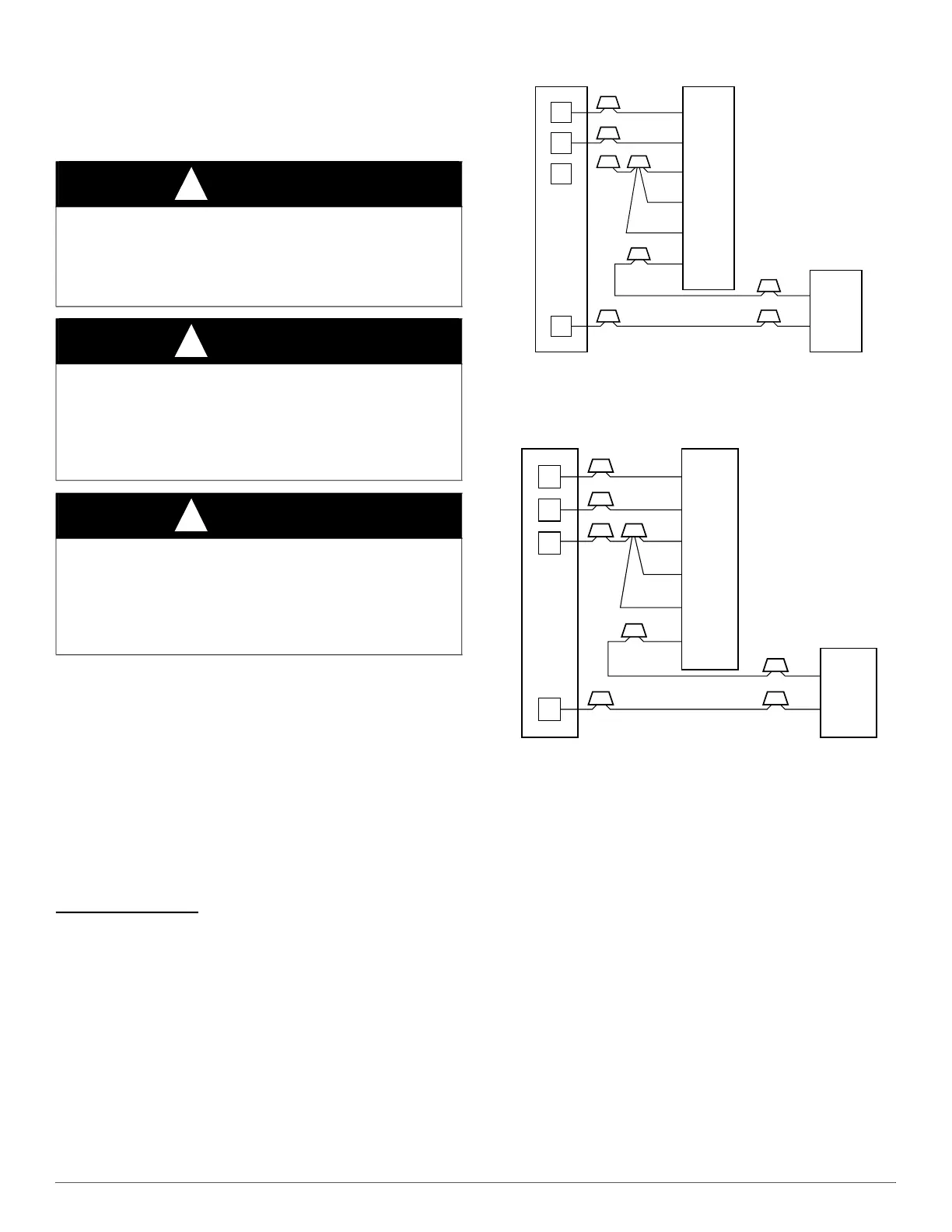
Fig. 9 – Wiring Layout Air Conditioning Unit
(Cooling Only)
A94059
Fig. 10 – Wiring Layout Air Conditioning Unit
(Cooling and 1-Stage Heat)
WARNING
!
PERSONAL OR EQUIPMENT DAMAGE HAZARD.
Failure to follow this warning could result in personal injury, death,
and/or unit damage.
Provide training to installation personnel to follow national and local
electrical codes.
WARNING
!
ELECTRICAL SHOCK OR UNIT DAMAGE HAZARD
Failure to follow this warning could result in personal injury, death,
and/or unit damage.
If a disconnect switch is to be mounted on unit, select a location where
drill and fasteners will not contact electrical or refrigeration
components.
WARNING
!
ELECTRICAL SHOCK HAZARD
Failure to follow this warning could result in personal injury or death.
Field wires on the line side of the disconnect found in the fan coil unit
remain live, even when the pull-out is removed. Service and
maintenance to incoming wiring cannot be performed until the main
disconnect switch (remote to the unit) is turned off.
R
G
W
Y
THERMOSTAT
RED
GRY
WHT
BLU
VIO
BRN
WHT
R
G
W
2
W
3
E
C
FAN COIL
(CONTROL)
C
Y
AIR COND.
R
G
W
Y
THERMOSTAT
R
G
W
2
W
3
E
C
FAN COIL
(CONTROL)
C
Y
AIR COND.
RED
GRY
WHT
WHT
BLU
VIO
BRN