PG92MSA: Installation, Start-up, Operating and Service and Maintenance Instructions
Manufacturer reserves the right to change, at any time, specifications and designs without notice and without obligations.
39
3. For each pipe, multiply the number of elbows by the equivalent
length for the type of elbow used. Record the equivalent length of
all the elbows for each pipe.
4. If a Tee is used on the termination (Alberta and Saskatchewan,
when required) record the equivalent length of the Tee used.
5. Calculate Total Equivalent Vent Length by adding the equivalent
lengths of the fittings to the lengths of the individual vent and
combustion air pipes.
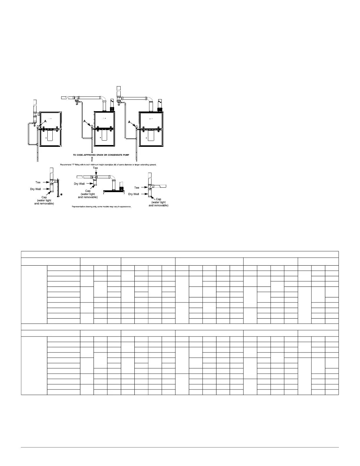
A170122A
Fig. 51 – Recommended Combustion Air Inlet Moisture Trap
6. When using polypropylene venting systems with flexible vent
pipes, perform adjustments for the equivalent length of the flexible
vent pipe to the calculated total equivalent venting system length.
See the polypropylene vent system manufacturer’s instructions for
details.
7. Select a diameter of vent pipe from Table 14 and note the
Maximum Equivalent Vent Length (MEVL) shown for that
application for that specific furnace input size. Compare the Total
Equivalent Vent Length (TEVL) to the MEVL:
8. If the Total Equivalent Vent Length is shorter than the Maximum
Equivalent Vent Length for the diameter of pipe chosen, then that
diameter of pipe selected may be used.
9. If the Total Vent Length is longer than the Maximum Equivalent
Vent Length for the diameter of pipe chosen, that diameter pipe
MAY NOT be used for venting the furnace. Try the next larger
diameter pipe
.
NOTE: If the calculated Total Equivalent Vent Lengths results in
different diameter pipes for the vent and combustion air, select the larger
diameter for both pipes.
NOTE: If the Maximum Vent Length for diameter of the pipe selected is
longer than the measured length and the equivalent length of all the
fittings and terminations (TEVL), recalculate Total Equivalent Vent
Length using the next smaller diameter. If the Maximum Equivalent
Vent Length is still longer than the longer TEVL of the vent pipe or
combustion air pipe, then that diameter of pipe selected may be used.
When installing vent systems pipe lengths of 10 ft. (3 M) or less, use the
smallest allowable pipe diameter. Using a pipe size greater than required
for short venting systems may result in loss of efficiency, incomplete
combustion, flame disturbance, or flame sense lockout.
For vent systems longer than 10 ft. (3 M), any larger diameter vent pipe
shown in Table 14 FOR THAT SIZE FURNACE may be used.
Table 14 – Maximum Equivalent Vent Length
NOTE: Maximum Equivalent Vent Length (MEVL) includes standard and concentric vent termination and does NOT include elbows. Use Table 15 -
Deductions from Maximum Equivalent Vent Length to determine allowable vent length for each application.
1. Inducer Outlet Restrictor disk (P/N 337683-401; 1.25-in. (32 mm) Dia.) shipped in the loose parts bag or available through Replacement Components required under 10-ft. (3 M) TEVL in
all orientations. Required for installations from 0 - 2000 (0 to 610 M) above sea level. Failure to use an outlet restrictor may result in flame disturbances or flame sense lock-out.
2. Inducer Outlet Restrictor disk (P/N 337683-401; 1.25-in. (32 mm) Dia.) available through Replacement Components required for no greater than 5-ft. (1.5 M) TEVL in downflow and
horizontal orientations only. Required for installations from 0 - 2000 (0 to 610 M) above sea level.
3. Inducer Outlet Restrictor disk (P/N 337683-401; 1.50-in. (38 mm) Dia.) available through Replacement Components required for no greater than 5-ft. (1.5 M) TEVL in downflow and
horizontal orientations only. Required for installations from 0 - 2000 (0 to 610 M) above sea level.
Single Stage 92% - Ft.
Unit Size
40,000
1
60,000
2
80,000
100,000
3
120,000
3
Altitude
(feet)
Pipe Dia. (in) 1 ½ 2 2 ½ 1 ½ 2 2 ½ 3 1 ½ 2 2 ½ 3 4 2 2 ½ 3 4 2 ½ 3 4
0-2000 20 85 185
20
100 175 200 15 55 130 175 200 20 80 175 200
10
75 185
2001-3000
15
80 175 95 165 185
10
49
125 165 185
15 75
165 185 70 175
3001-4000
70
160 16 90 155 175 115 155 175
155
175 5 65 165
4001-4500
10
155
15
85
150
170
44 110
150 165
10
70 170
N/A
60
160
4501-5000 145 80 165 145 160
65
150 165
5001-6000 60 130 75 140 155 41 100 135 150 140 155 155
6001-7000
5
55 120 13 70 130 145
N/A
38
90
125 140 60 135 145 50 140
7001-8000 50 110 10 65 120 135 36 120 125
N/A
55 125 135 46 130
8001-9000
N/A
30 95 5 60 115 125 33 80 110 115 50 115 125 43 120
9001-10000 25 85 N/A 55 105 115 30 75 100 105 45 100 115 39 115
Single Stage 92% - Meters
Unit Size
40,000
1
60,000
2
80,000
100,000
3
120,000
3
Altitude
(meters)
Pipe Dia. (mm) 38 51 64 38 5 64 76 38 51 64 76 102 51 64 76 102 64 76 102
0-610 6.0 25.9 56.3
6.0
30.4 53.3 60.9 4.5 16.7 39.6 53.3 60.9 6.0 24.3 53.3 60.9
3.0
22.8 56.3
611-914
4.5
24.3 53.3 28.9 50.2 56.3
3.0
14.9
38.1 50.2 56.3
4.5
22.8 50.2 56.3 21.3 53.3
915-1219
21.3
48.7 4.8 27.4 47.2 53.3 35.0 47.2 53.3 0.0
47.2
53.3 1.5 19.8 50.2
1220-1370
3.0
47.2
4.5
25.9
45.7
51.8
13.4
33.5 45.7 50.2
3.0
21.3 51.8
N/A
18.2
48.7
1371-1524 44.1 24.3 50.2 0.0 44.1 48.7 19.8 45.7 50.2
1525-1829 18.2 39.6 22.8 42.6 47.2 12.4 30.4 41.1 45.7 0.0 42.6 47.2 47.2
1830-2134
1.5
16.7 36.5 3.9 21.3 39.6 44.1
N/A
11.5 27.4 .1 42.6 18.2 41.1 44.1 15.2 42.6
2135-2438 15.2 33.5 3.0 19.8 36.5 41.1 10.9 0.0 36.5 38.1
N/A
16.7 38.1 41.1 14.0 39.6
2439-2743
N/A
9.1 28.9 1.5 18.2 35.0 38.1 10.0 24.3 33.5 35.0 15.2 35.0 38.1 13.1 36.5
2744-3048 7.6 25.9 N/A 16.7 32.0 35.0 9.1 22.8 30.4 32.0 13.7 30.4 35.0 11.8 35.0