Manufacturer reserves the right to discontinue, or change at any time, specifications or designs without notice and without incurring obligations.
PC 111 Catalog No. 533-80072 Printed in U.S.A. Form 38-54SI Pg 1 11-02 Replaces: 38-52SI
Book 1 4
Ta b 3 a 2a
Installation, Start-Up and
Configuration Instructions
Part Number 33
CSPREMLK
CONTENTS
Page
SAFETY CONSIDERATIONS
. . . . . . . . . . . . . . . . . . . . . . 1
GENERAL
. . . . . . . . . . . . . . . . . . . . . . . . . . . . . . . . . . . . . . .1,2
INSTALLATION
. . . . . . . . . . . . . . . . . . . . . . . . . . . . . . . . 2-26
Inspection
. . . . . . . . . . . . . . . . . . . . . . . . . . . . . . . . . . . . . . . . 2
PremierLink Controller Hardware
. . . . . . . . . . . . . . . . . 2
Field-Supplied Hardware
. . . . . . . . . . . . . . . . . . . . . . . . . 2
• SPACE TEMPERATURE (SPT) SENSOR
• SUPPLY AIR TEMPERATURE (SAT) SENSOR
• INDOOR AIR QUALITY CO
2
SENSOR
• OUTDOOR AIR QUALITY CO
2
SENSOR
• OUTDOOR AIR TEMPERATURE SENSOR
• OUTDOOR AIR ENTHALPY SWITCH
• RETURN AIR ENTHALPY SENSOR
Mount PremierLink Control
. . . . . . . . . . . . . . . . . . . . . . . 2
•LOCATION
• MOUNTING
PremierLink Controller Inputs and Outputs
. . . . . . 3
Control Wiring
. . . . . . . . . . . . . . . . . . . . . . . . . . . . . . . . . . . . 3
Install Sensors
. . . . . . . . . . . . . . . . . . . . . . . . . . . . . . . . . . . 9
• SPACE TEMPERATURE (SPT) SENSOR
INSTALLATION
• SUPPLY AIR TEMPERATURE (SAT) SENSOR
INSTALLATION
• INDOOR AIR QUALITY CO
2
SENSOR
INSTALLATION
• OUTDOOR AIR QUALITY CO
2
SENSOR
INSTALLATION
• OUTDOOR AIR TEMPERATURE SENSOR
Connect to CCN Communication Bus
. . . . . . . . . . . 18
• COMMUNICATIONS BUS WIRE SPECIFICATIONS
Enthalpy and Differential Enthalpy Control
. . . . . . 18
• ENTHALPY SWITCH/RECEIVER
• OUTDOOR AND RETURN AIR ENTHALPY
SENSOR
Economizer
. . . . . . . . . . . . . . . . . . . . . . . . . . . . . . . . . . . . . 21
• Q769B
• Q769C
Economizer with Johnson 4 to 20 mA
Actuator
. . . . . . . . . . . . . . . . . . . . . . . . . . . . . . . . . . . . . . 24
• DRIVE DIRECTION
• SWITCH SELECTION
•WIRING
START-UP
. . . . . . . . . . . . . . . . . . . . . . . . . . . . . . . . . . . . 26-28
Perform System Check-Out
. . . . . . . . . . . . . . . . . . . . . 26
Initial Operation and Test
. . . . . . . . . . . . . . . . . . . . . . . . 26
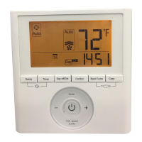
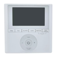
Install Navigator™ Display Module
. . . . . . . . . . . . . 26
Password Protection
. . . . . . . . . . . . . . . . . . . . . . . . . . . . 28
Forcing Values and Configuring Items
. . . . . . . . . . 28
Page
CONFIGURATION
. . . . . . . . . . . . . . . . . . . . . . . . . . . . 28-42
Points Display Screen
. . . . . . . . . . . . . . . . . . . . . . . . . . . 28
Thermostat Control Input Screen
. . . . . . . . . . . . . . . . 30
Alarm Service Configuration Screen
. . . . . . . . . . . . 30
Controller Identification Screen
. . . . . . . . . . . . . . . . . 31
Holiday Configuration Screen
. . . . . . . . . . . . . . . . . . . 31
Occupancy Configuration Screen
. . . . . . . . . . . . . . . 32
Set Point Screen
. . . . . . . . . . . . . . . . . . . . . . . . . . . . . . . . 32
Service Configuration Selection Screen
. . . . . . . . . 33
PremierLink Configuration Screen
. . . . . . . . . . . . . . 37
Occupancy Maintenance Screen
. . . . . . . . . . . . . . . . 39
Maintenance Screen
. . . . . . . . . . . . . . . . . . . . . . . . . . . . 40
SAFETY CONSIDERATIONS
GENERAL
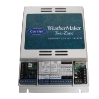
The PremierLink Controller is a field retrofit split system
control compatible with the Carrier Comfort Network (CCN).
This control is designed to allow users the access and ability to
change factory-defined settings thus expanding the function of
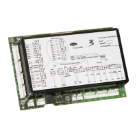
the standard unit control board. The complete PremierLink
package (part number 33CSPREMLK) consists of a control
circuit board with plastic cover and label, wire harnesses, spade
connectors, wire nuts and 4 mounting screws.
SAFETY NOTE
Air-handling equipment will provide safe and reliable service
when operated within design specifications. The equipment
should be operated and serviced only by authorized person-
nel who have a thorough knowledge of system operation,
safety devices and emergency procedures.
Good judgement should be used in applying any manufac-
turer’s instructions to avoid injury to personnel or damage to
equipment and property.
Disconnect all power to the unit before performing mainte-
nance or service. Unit may automatically start if power is
not disconnected. Electrical shock and personal injury
could result.
Damage to equipment may result. An individual field-
supplied 24-vac power transformer is required for each
PremierLink controller. The transformer must be less than
100 va to meet UL (Underwriters’ Laboratories) Class 2.
PremierLink™
Retrofit Split System
Controller