Example:
3—230 or 208–230 or 208/230, 1 Phase, 60 Hertz
5—230 or 208–230 or 208/230, 3 Phase, 60 Hertz
6—460, 3 Phase, 60 Hertz
7—220/240, 1 Phase, 50 Hertz
8—220, 3 Phase, 50 Hertz
9—380/415, 3 Phase, 50 Hertz
Position 13—Series
New units have a 0. As major component variations occur,
including compressor changes, fan motors, coil circuitry size, etc.,
the change is identified by increasing this digit in increments of 1.
Position 14—Packaging
On split-system products, this digit will be 0.
Positions 15 and 16—Not Used
These positions will contain dashes (———).
Step 2—Serial Number Identification
The unit serial number has 10 positions containing groups of
numbers and a letter that indicate specific information about the
unit. Listed below is the breakdown of the 10 positions.
Positions 1 and 2—Week of Manufacture
Example:
01—First week of a year
52—Last week of a year
Positions 3 and 4—Year of Manufacture
Example:
94—1994
Position 5—Manufacturing Site
Example:
A–Indianapolis
E–Collierville
Positions 6 through 10—Serial Number
CABINET
Certain maintenance routines and repairs require removal of
cabinet panels. There are 4 basic cabinet designs for air condition-
ers and heat pumps. (See Fig. 8.) The horizontal discharge unit will
be discussed in a separate section of this manual.
Step 1—Remove Top Cover-WeatherMaker™
1. Turn off all power to outdoor and indoor units.
2. Remove screws holding top cover to coil grille and corner
posts.
3. Remove access panel.
4. Remove information plate.
5. Disconnect fan motor wires, cut wire ties, and remove wire
ties from control box. Refer to unit-wiring label.
6. Lift top cover from unit.
7. Reverse sequence for reassembly.
Step 2—Remove Fan-Motor Assembly-WeatherMaker™
1. Perform items 1 through 6 above.
2. Remove nuts holding fan-motor top cover.
3. Remove motor and fan blade assembly.
4. Reverse sequence for reassembly.
5. Prior to applying power, check that fan rotates freely.
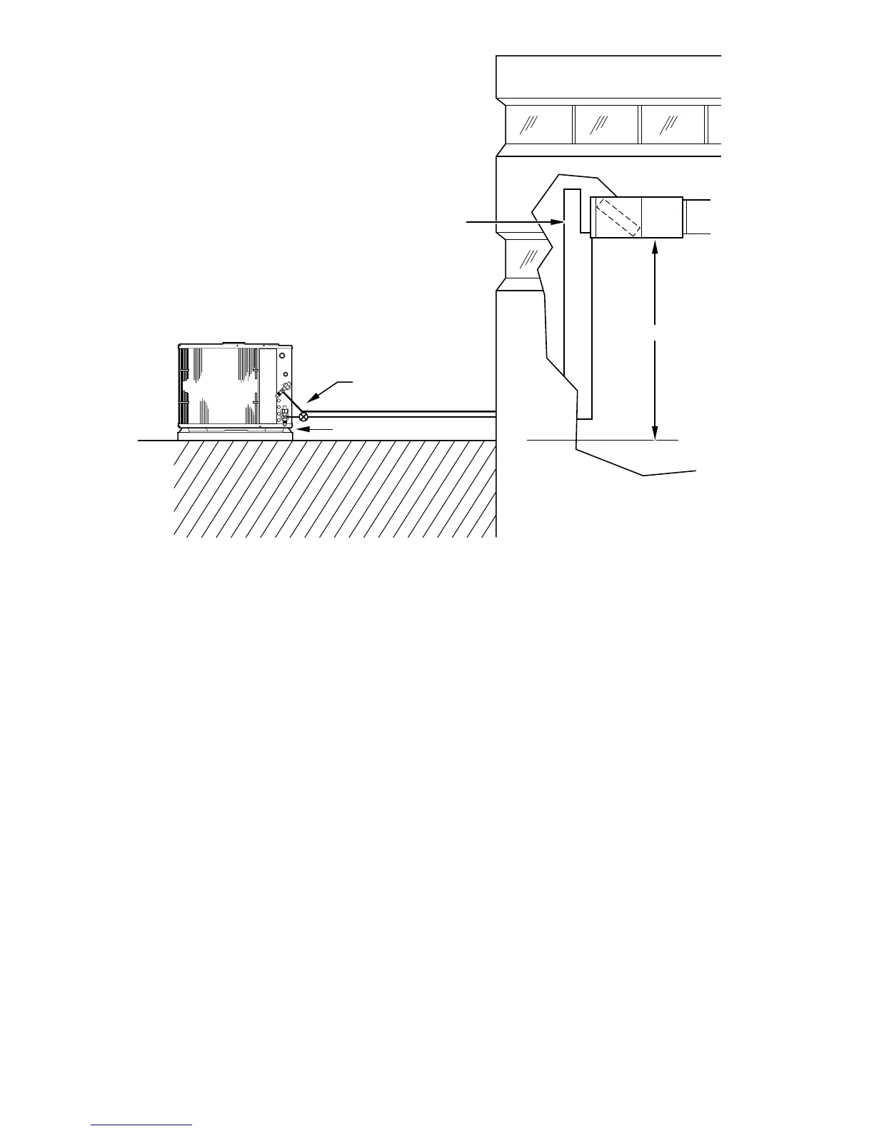
Fig. 6—Application with Air Conditioner or Heat Pump Installed with Indoor Unit Above Outdoor Unit
A90076
HEAT PUMP ONLY
50' MAX.
GROUND LEVEL
TRAP
10
 Loading...