Step 6—2–Speed Applications
Outdoor units may be connected to indoor section using accessory
tubing package or field-supplied refrigerant grade tubing or correct
size and condition. In long-line applications, 2–speed units are
handled basically the same way as the single-speed units. There are
2 major differences:
1. For tubing up to 100 ft:
Liquid tube diameters and refrigerant connection diameters for
all sizes are 3/8 in.
Vapor tube diameter for the 036 and 048 is 7/8 in.; 060 is
1–1/8
Vapor refrigerant connection diameter for all sizes is 7/8 in.
DO NOT INSTALL EQUIVALENT INTERCONNECTING
TUBING LENGTHS GREATER THAN 100 FT.
2. Do not increase or decrease tubing sizes.
For other applications see the previous sections under Long-Line
Guidelines.
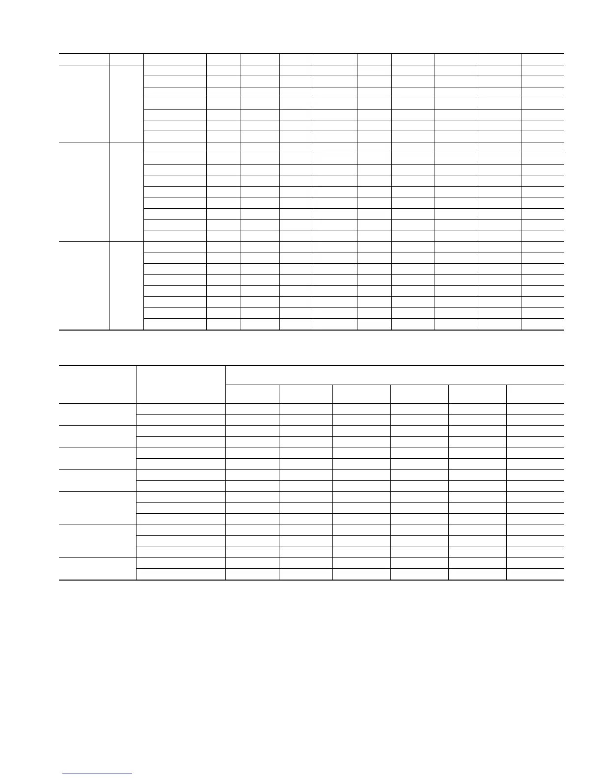
Table 4—Wind Baffle Dimensions for Cube Units (In.)
UNIT SIZE AA UNIT HEIGHT A B C D E F G. H. J
Small 18
21-15/16 19-7/8 13-3/4 28-1/8 10-11/16 20-1/4 11-11/16 3-13/16 19-13/16 17-13/16
23-15/16 21-7/8 13-3/4 28-1/8 10-11/16 20-1/4 11-11/16 3-13/16 21-13/16 19-13/16
25-15/16 23-7/8 13-3/4 28-1/8 10-11/16 20-1/4 11-11/16 3-13/16 23-13/16 21-13/16
27-15/16 25-7/8 13-3/4 28-1/8 10-11/16 20-1/4 11-11/16 3-13/16 25-13/16 23-13/16
29-15/16 27-7/8 13-3/4 28-1/8 10-11/16 20-1/4 11-11/16 3-13/16 27-13/16 25-13/16
31-15/16 29-7/8 13-3/4 28-1/8 10-11/16 20-1/4 11-11/16 3-13/16 29-13/16 27-13/16
33-15/16 31-7/8 13-3/4 28-1/8 10-11/16 20-1/4 11-11/16 3-13/16 31-13/16 29-13/16
Medium 22-1/2
21-15/16 19-7/8 18-5/16 32-5/8 10-11/16 24-3/4 16-3/16 8-1/4 19-13/16 17-13/16
23-15/16 21-7/8 18-5/16 32-5/8 10-11/16 24-3/4 16-3/16 8-1/4 21-13/16 19-13/16
25-15/16 23-7/8 18-5/16 32-5/8 10-11/16 24-3/4 16-3/16 8-1/4 23-13/16 21-13/16
27-15/16 25-7/8 18-5/16 32-5/8 10-11/16 24-3/4 16-3/16 8-1/4 25-13/16 23-13/16
29-15/16 27-7/8 18-5/16 32-5/8 10-11/16 24-3/4 16-3/16 8-1/4 27-13/16 25-13/16
31-15/16 29-7/8 18-5/16 32-5/8 10-11/16 24-3/4 16-3/16 8-1/4 29-13/16 27-13/16
33-15/16 31-7/8 18-5/16 32-5/8 10-11/16 24-3/4 16-3/16 8-1/4 31-13/16 29-13/16
35-15/16 33-7/8 18-5/16 32-5/8 10-11/16 24-3/4 16-3/16 8-1/4 33-13/16 31-13/16
37-15/16 35-7/8 18-5/16 32-5/8 10-11/16 24-3/4 16-3/16 8-1/4 35-13/16 33-13/16
Large 30
25-15/16 23-7/8 25-3/4 40-1/8 10-11/16 32-1/4 23-11/16 15-13/16 23-13/16 21-13/16
27-15/16 25-7/8 25-3/4 40-1/8 10-11/16 32-1/4 23-11/16 15-13/16 25-13/16 23-13/16
29-15/16 27-7/8 25-3/4 40-1/8 10-11/16 32-1/4 23-11/16 15-13/16 27-13/16 25-13/16
31-15/16 29-7/8 25-3/4 40-1/8 10-11/16 32-1/4 23-11/16 15-13/16 29-13/16 27-13/16
33-15/16 31-7/8 25-3/4 40-1/8 10-11/16 32-1/4 23-11/16 15-13/16 31-13/16 29-13/16
35-15/16 33-7/8 25-3/4 40-1/8 10-11/16 32-1/4 23-11/16 15-13/16 33-13/16 31-13/16
37-15/16 35-7/8 25-3/4 40-1/8 10-11/16 32-1/4 23-11/16 15-13/16 35-13/16 33-13/16
39-15/16 37-7/8 25-3/4 40-1/8 10-11/16 32-1/4 23-11/16 15-13/16 37-13/16 35-13/16
Table 5—Estimated Percentage of Nominal Cooling-Capacity Losses*
UNIT
NOMINAL
SIZE
(BTUH)
LONG-LINE
VAPOR-LINE
DIAMETER
(IN.)†
EQUIVALENT LINE LENGTH (FT)
50 75 100 125 150 175
18,000
5/8 57 9 121214
3/4 134557
24,000
5/8 6913161922
3/4 011234
30,000
5/8 6810131517
3/4 234567
36,000
3/4 710141721NR
7/8 2 4 6 8 10 11
42,000
3/4 71013172023
7/8 3 4 6 7 8 10
1-1/8 0 0 1122
48,000
3/4 10 14 18 22 NR NR
7/8 4 6 7 9 11 13
1-1/8 0 0 1122
60,000
7/8 7911141619
1-1/8 1 2 2334
*The estimated percentage of cooling capacity that must be subtracted from the Detailed Cooling Capacities data specified in outdoor unit-presale literature for any given
indoor/outdoor combination.
†Vapor-line diameter that may be selected for a long-line application. If smaller vapor lines are selected but not specified within the table, large capacity losses will occur
and defrost capabilities will be reduced. If larger vapor lines are selected but not specified within the table, refrigerant oil return will be impaired due to velocity losses.
N/R—Not recommended due to excessive loss of capacity.
7
 Loading...