44
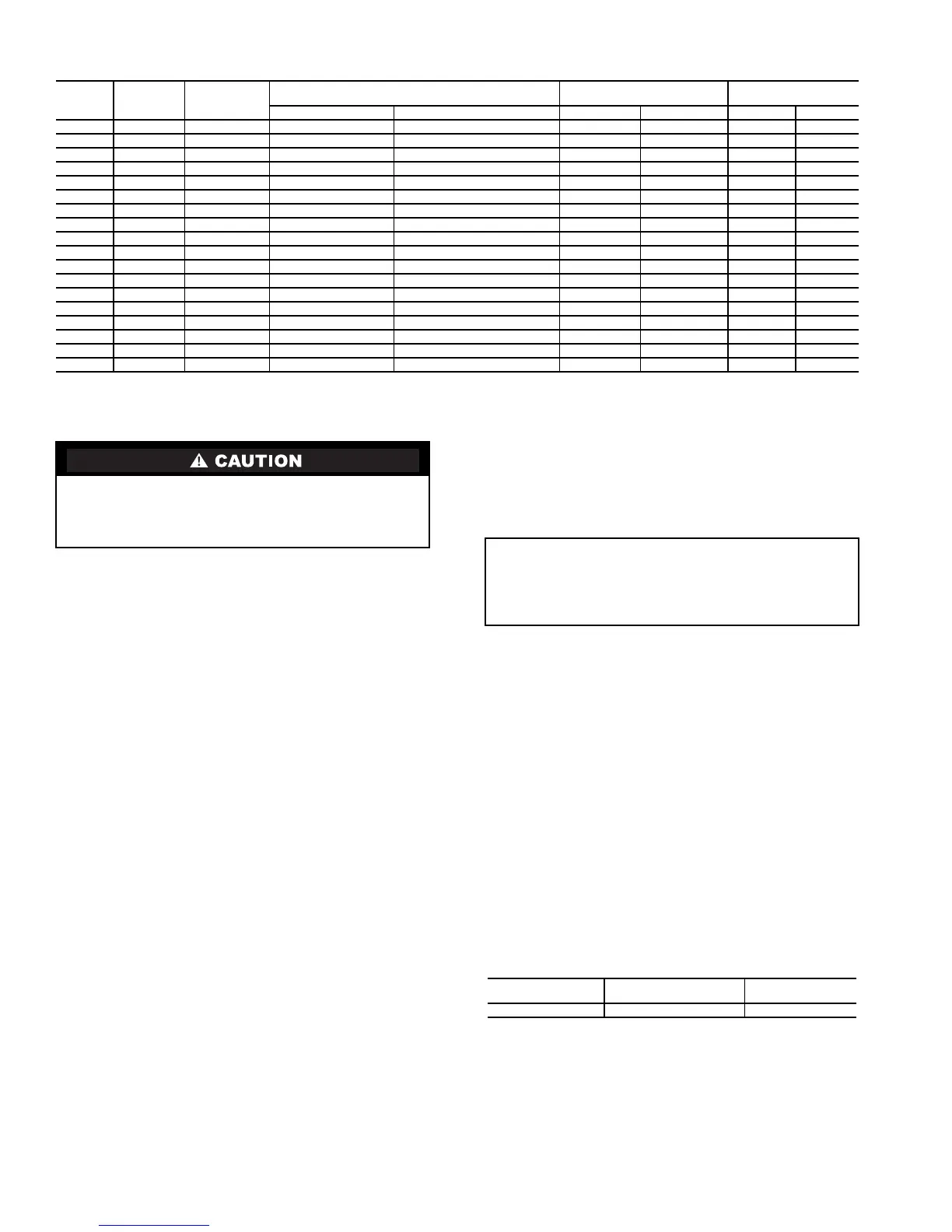
Table 3B — Duplex Unit Operating Range
Step 3 — Piping Connections —
See Fig. 29-35 for
piping applications.
GENERAL — The factory-installed victaulic connections al-
low clamp-on connection of water lines to the coolers in all
30GXN,R units. See Tables 4 and 5 for proper piping align-
ment with the victaulic flanges. Each unit is shipped with
2 flange assemblies (Fig. 29) with integral nozzles, 2 gaskets
(located in control box) and one flow sensor. See Fig. 30. The
flow sensor is factory-installed in the side of the entering fluid
nozzle.
DUPLEX UNIT PIPING CONNECTIONS — The 30GXN,R
duplex units require a field piping connection between the two
modules. All duplex 30GXN,R chillers have standard 8 in.
(219.1 mm) diameter pipe connections. Victaulic style grooved
pipe fittings are recommended for the interconnecting piping to
ensure no weld slag enters the cooler. A flexible coupling
(Braided Stainless Flex Hose SVG8 or Butyl Rubber Unaflex
Style 1000 or similar) is required between the two modules.
See Fig. 11-25. Tables 4 and 5 provide alignment criteria for
the Victaulic and Flex-Hose couplings. Piping details for use
with the Duplex Trim Kit are shown on the Typical Duplex
Connection Piping diagram in Fig. 32B and 33.
COOLER FLUID, VENT, AND DRAIN — The inlet (re-
turn) fluid connection is always the lower of the 2 cooler con-
nections. See Fig. 1-25 for locations. A screen strainer with a
minimum size of 20 mesh must be installed ahead of the cooler
inlet to prevent debris from damaging internal tubes of the
cooler. Outlet (supply) fluid connection is the upper connection
of the 2 cooler connections.
The cooler has victaulic connections to connect the field-
supplied piping. Plan the piping arrangement in accordance
with good piping practices and so that the piping does not cross
in front of the cooler head. Use flexible connections on cooler
piping to reduce vibration transmission. Offset the piping to
permit removal of the cooler head for maintenance. Install
pipe hangers where needed. Make sure no weight or stress is
placed on the water nozzle.
Standard piping alignment criteria is shown in Tables 4
and 5.
Provide openings in fluid piping for pressure gages and
thermometers (if used). These openings should be 5 to 10 pipe
diameters from the unit leaving water nozzle. For thorough
mixing and temperature stabilization, wells in the leaving fluid
pipe should extend at least 2 in. (50 mm) into the pipe.
Although cooler has an air vent, it is recommended that a
field-supplied air vent be installed in the system to facilitate
servicing. Field-supplied shut-off and balancing valves should
also be installed to facilitate servicing and flow balancing. Lo-
cate valves in return and supply fluid lines as close to the chill-
er as possible. Locate air vent at highest point of the cooler
fluid system. See Fig. 32A and 32B.
Provide drain connections at all low points to permit com-
plete drainage of the system.
A thermal flow sensor is factory installed in the entering
fluid nozzle. The sensor is factory wired. If a cooler pump in-
terlock is used, connect the interlock to terminals TB5-1, 2.
The factory-installed flow sensor and cooler interlock must be
wired in series.
Table 4 — Victaulic Connection Alignment
30GXN,R COOLER
NO. OF
PASSES
MAX. COOLER TEMPERATURE
DIFFERENCE
REFERENCE
MIN FLOW RATE
NOMINAL
FLOW RATE
F C Gpm L/s Gpm L/s
283 STD 1 20 11.1 329 20.8 658 41.5
303 STD 1 20 11.1 347 21.9 694 43.8
328 STD 1 20 11.1 382 24.1 764 48.2
353 STD 1 20 11.1 420 26.5 839 53.0
370 STD 1 20 11.1 502 31.7 879 55.5
373 STD 1 20 11.1 444 28.0 889 56.1
390 STD 1 20 11.1 588 37.1 909 57.3
393 STD 1 20 11.1 461 29.1 921 58.1
415 STD 1 20 11.1 588 37.1 974 61.4
418 STD 1 20 11.1 475 30.0 950 59.9
450 STD 1 20 11.1 502 31.7 1031 65.0
453 STD 1 20 11.1 512 32.3 1025 64.7
475 STD 1 20 11.1 542 34.2 1085 68.4
478 STD 1 20 11.1 546 34.4 1091 68.8
500 STD 1 20 11.1 571 36.0 1141 72.0
503 STD 1 20 11.1 579 36.5 1158 73.0
525 STD 1 20 11.1 601 37.9 1202 75.8
528 STD 1 20 11.1 607 38.3 1214 76.6
Remove chilled water flow switch, entering and leaving
water thermistors before welding connecting piping. Rein-
stall flow switch and thermistors after welding is complete.
Failure to remove these devices may cause unit damage.
IMPORTANT: Installation of a cooler pump interlock is
recommended to aid in preventing potential system dam-
age due to loss of fluid flow. Install on TB5-1 to TB5-2 and
connect pump interlock. See Field Control Power Connec-
tions section.
PIPE SIZE NOM. in.
(ACTUAL mm)
PIPE END SEPARATION
in. (mm)
PIPE ALIGNMENT
in./Ft (mm/m)
8 (219.1) 0-0.13 (0-3.2) 0.27 (21)