53
Duplex Chiller Control Configuration —
See
Fig. 36-39 and Table 6. The dual chiller routine is available for
the control of two units supplying chiller fluid on a common
loop. One chiller must be configured as the master chiller, the
other as the slave chiller. The module B chiller is the master
and the module A chiller is the slave.
NOTE: Chiller module B must be configured on site as the
master chiller and module A must be configured on site as the
slave chiller for all 30GXN,R duplex chiller applications. Field
installation of communication wiring is required. Connections
can be made to the CCN screw terminals on TB3 in both
chillers.
The master chiller will be configured with a slave chiller at
address 2. The chillers will be configured for series fluid flow.
The master and slave chillers cannot have the same CCN
address (CCNA, Configuration mode under OPT2). In addi-
tion, the chillers must reside on the same CCN bus. The master
chiller controls the slave chiller by changing its mode (STAT,
control mode) and its operating setpoint (CTPT, control point).
Any energy management functions need only be connected to
the Master chiller. The EMM accessory has to be installed in
the Master chiller only.
The master chiller is now configured for dual chiller opera-
tion. To configure the slave chiller, only the LLEN, MSSL, and
PARA variables need to be set. Set the Lead Lag Enable
(LLEN) variable to ENBL. Set the Master Slave Select
(MSSL) variable to SLVE. Set the Parallel (PARA) variable to
NO. The variables SLVA, LLBL, LLBD and LLDY are not
used by the slave chiller.
Table 6 — Duplex Configuration
LEGEND
N/R — Not Required
*Set to desired control method: switch (0); 7-day occupancy (1); CCN occupancy (2); CCN (3). Slave is
always configured to switch (0).
†Optional.
MODE SUB-MODE ITEM DESCRIPTION MASTER SLAVE
Configuration
OPT2 CTRL Controls Method Switch* Switch*
CCNA CCN Address 1 2
RSET LLEN Lead/Lag Chiller Enable ENBL ENBL
MSSL Master/Slave Select MAST SLVE
SLVA Slave Address 2 N/R
LLBL† Lead/Lag Balance Select
Master Leads - 0;
Slave Leads - 1;
Automatic - 2
N/R
LLBD† Lead/Lag Balance Data 168 hrs. N/R
LLDY† Lag Start Delay 5 min. N/R
PARA Parallel Configuration No No
RETURN
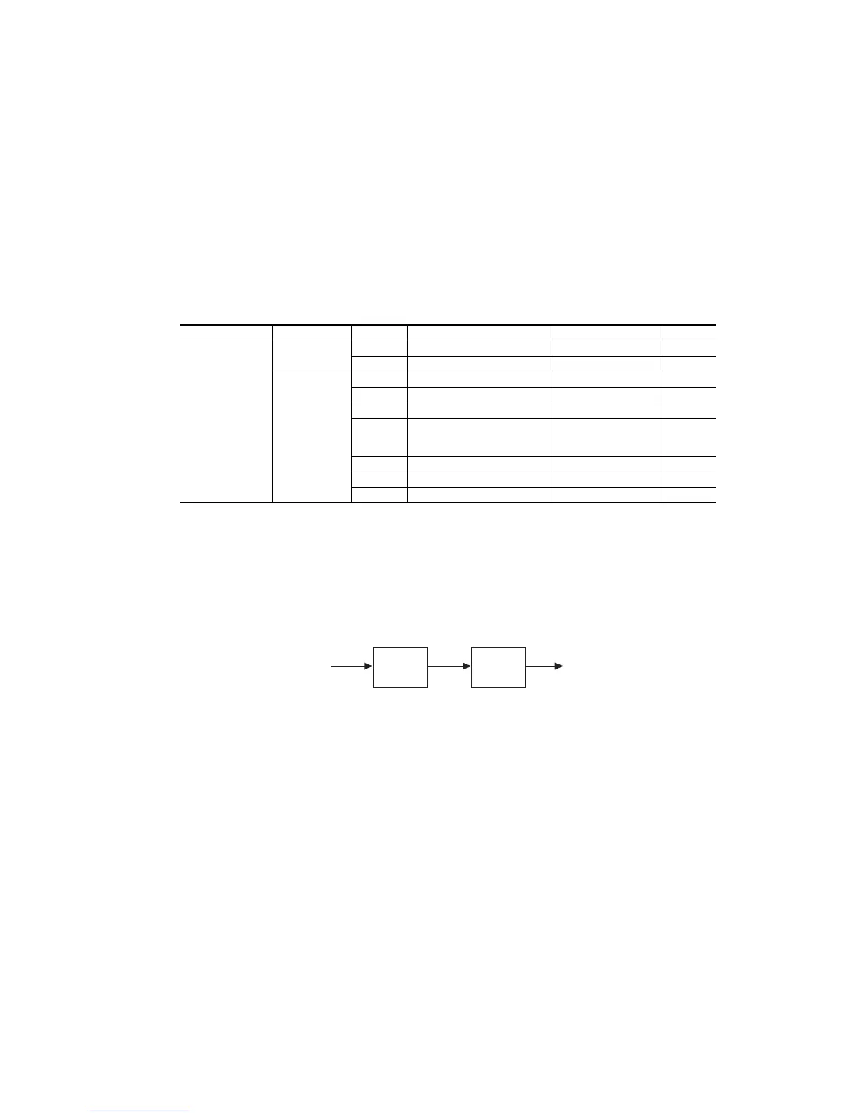
FLUID
LEAVING
FLUID
SLAVE
CHILLER
(module A)
MASTER
CHILLER
(module B)
Fig. 39 — Dual Chiller Piping Arrangement,
Series Fluid Flow