52
COMMUNICATIONS WIRING
LEGEND
A
—
Alarm
CWP
—
Chilled Water Pump
CWPI
—
Chilled Water Pump Interlock
EMM
—
Energy Management Module
FIOP
—
Factory-Installed Option
LWT
—
Leaving Water Thermistor
OAT
—
Outdoor-Air Thermistor
SPT
—
Space Temperature Thermistor
TB
—
Te r m i n a l B l o ck
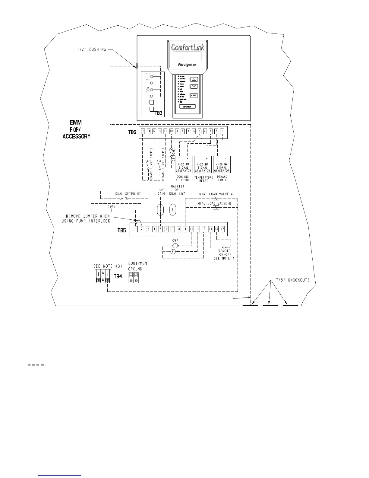
Field Control Wiring
Fig. 38 — Field Control Wiring
NOTES:
1. Power for control circuit should be supplied from a separate source through a field-
supplied disconnect (see Tables 7A-7E for maximum current protection requirements).
Connect control circuit power to terminals 1 and 2 of TB4. Control circuit conductors for
all units must be copper only.
2. Terminals 13 and 14 of TB5 are for field external connection for remote on-off. The
contacts must be capable of handling a 24-vac load up to 50 mA. For Dual Chiller installa-
tions, remote on-off contacts should be supplied to both modules.
3. Terminals 1 and 2 of TB5 are for Chilled Water Pump Interlock (CWPI) functions. If
added, remove jumper. The contacts must be rated for dry circuit application capable of
handling a 24-vac load up to 50 mA load. Chilled Water Flow Switch (CWFS) is factory
installed.
4. Terminals 10 and 12 of TB5 are for control of chilled water pump starter. The maximum
load allowed for the chilled water pump relay is 75-va sealed, 360-va inrush at 115 or
230 volt depending on control circuit voltage. Field power supply is not required.
5. Terminals 11 and 12 of TB5 are for alarm relay. The maximum load allowed for the alarm
relay is 75-va sealed, 360-va inrush at 115 or 230 volt depending on control circuit volt-
age. Field power supply is not required.
6. Make appropriate connections to TB6 as shown for energy management board options.
The contacts for Demand Limit and Ice Done options must be capable of handling a
24-vac load up to 50 mA.
7. All 30GXN,R duplex chillers have the EMM option mounted in the master chiller (B) only.
All remote chiller control interfaces are required on the master (B) chiller only.