46
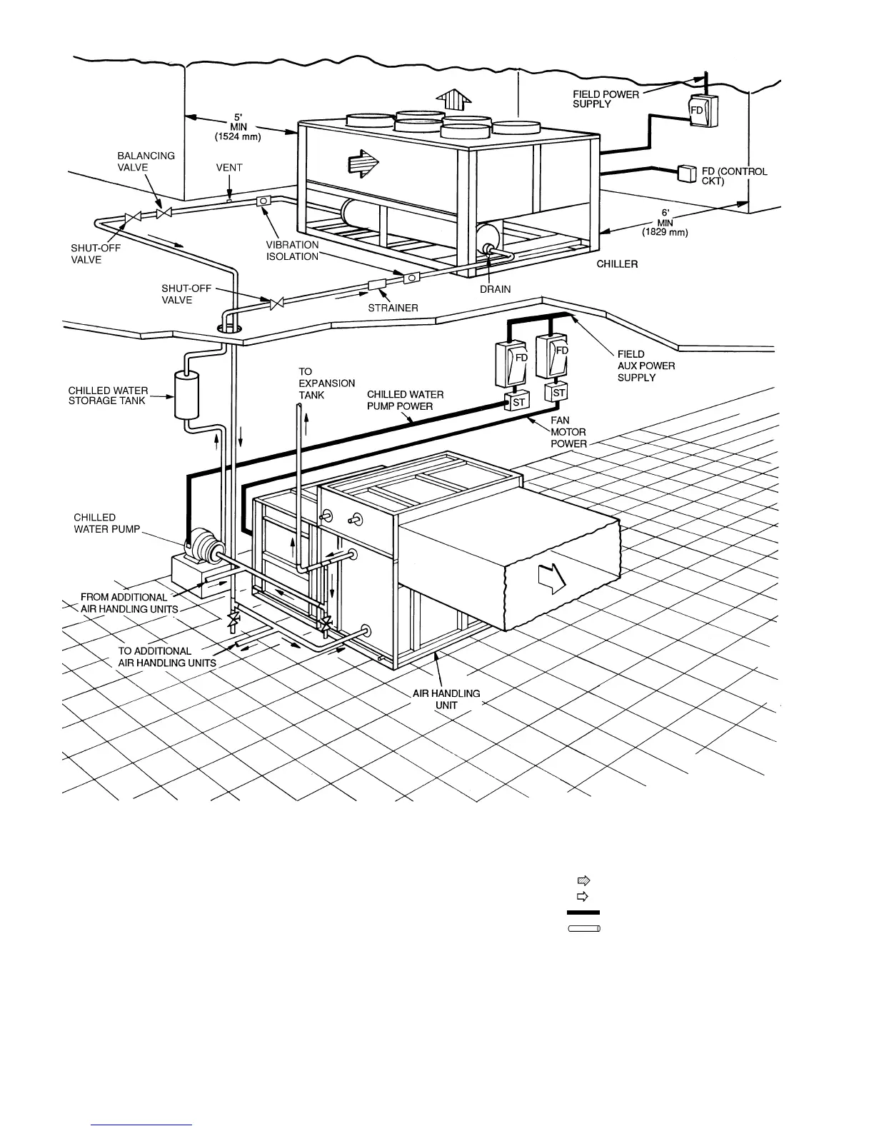
NOTES:
1. Chiller must be installed level to maintain proper compressor oil return and hydraulics.
2. Wiring and piping shown are general points-of-connection guides only and are not
intended for a specific installation. Wiring and piping shown are for a quick overview of
system and are not in accordance with recognized standards. Certified field wiring and
dimensional diagrams are available upon request. The 30GXN,R units should be
installed using certified drawings.
3. All wiring must comply with applicable local and national codes.
4. All piping must follow standard piping techniques. Refer to Carrier System Design Man-
ual or appropriate ASHRAE (American Society of Heating, Refrigeration, and Air Condi-
tioning Engineers) handbook for details.
Fig. 32A — Typical Piping and Wiring (30GXN,R106-135 Shown)
LEGEND
AUX —
Auxiliary
CKT —
Circuit
FD —
Field-Supplied Disconnect
ST —
Starter
Airflow Through Condenser
Airflow Through Air-Handling Unit
Power Wiring
Chilled Water Piping