R4A4S, R4A5S: Installation Instructions
Manufacturer reserves the right to change, at any time, specifications and designs without notice and without obligations.
8
Final Wiring Check
IMPORTANT: Check factory wiring and field wire connections to
ensure terminations are secured properly. Check wire routing to ensure
wires are not in contact with tubing, sheet metal, etc.
Compressor Crankcase Heater
When equipped with a crankcase heater, furnish power to heater a
minimum of 24 hr before starting unit. To furnish power to heater only,
set thermostat to OFF and close electrical disconnect to outdoor unit.
A crankcase heater is required if refrigerant tubing is longer than 80 ft.
(24 m) or when outdoor unit is 35 ft. (6 m) below indoor unit. Refer to
the Residential Piping and Long Line Guideline and Service Manual.
Install Electrical Accessories
Refer to the individual instructions packaged with kits or accessories
when installing.
Start-Up
Follow these steps to properly start up system:
1. After system is evacuated, fully open liquid and vapor service
valves.
2. Unit is shipped with valve stem(s) front seated (closed) and caps
installed. Replace stem caps after system is opened to refrigerant
flow. Replace caps finger-tight and tighten with wrench an
additional 1/12 turn.
3. Close electrical disconnects to energize system.
4. Set room thermostat at desired temperature. Be sure set point is
below indoor ambient temperature.
5. Set room thermostat to COOL and fan control to ON or AUTO
mode, as desired. Operate unit for 15 minutes. Check system
refrigerant charge.
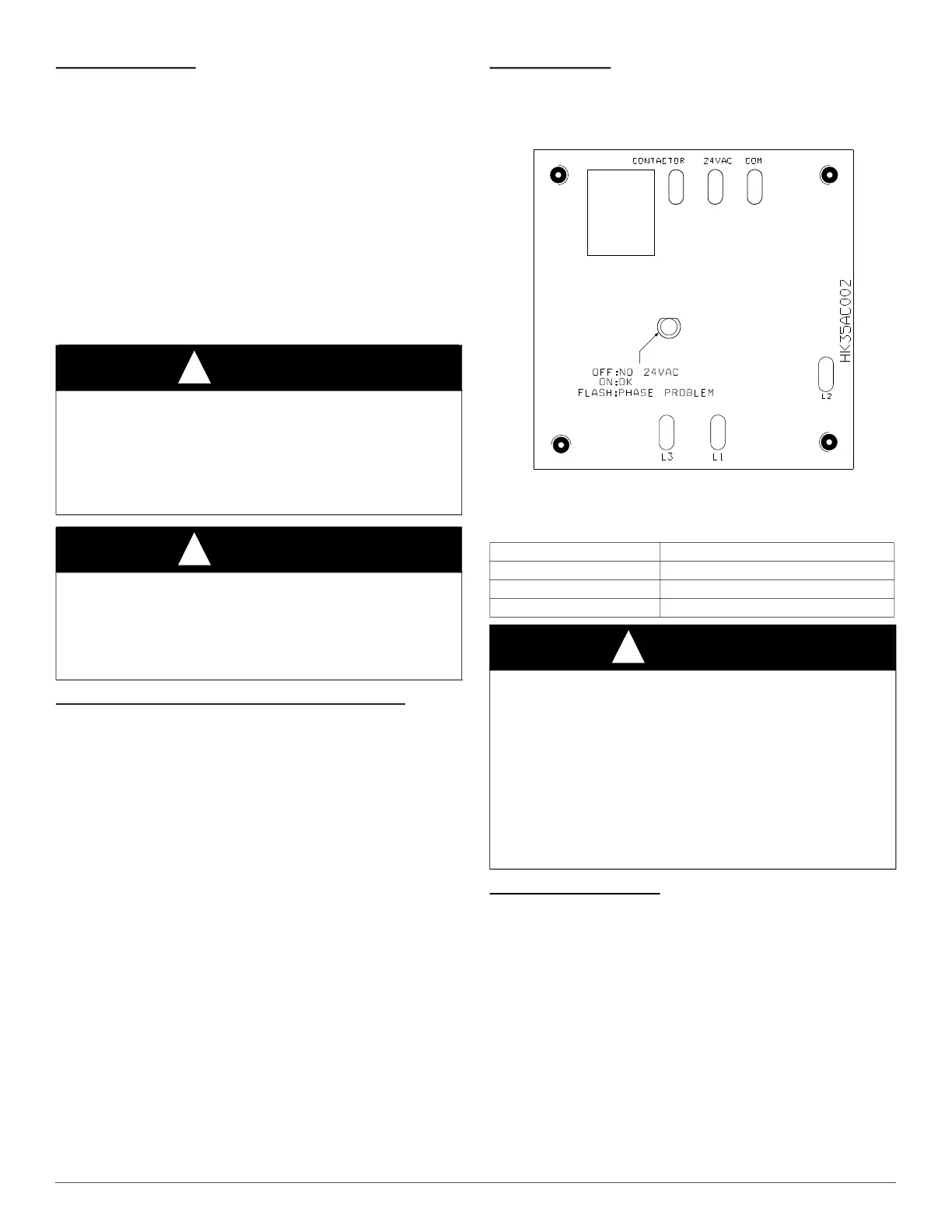
3-Phase Monitor
In 3-phase units a small circuit board is factory installed to monitor line
voltage. A small led will flash if a phase problem exists. See code
descriptions on monitor. If LED is flashing, disconnect power to unit
and interchange 2 field-wiring leads on unit contactor.
A00010
Fig. 8 – 3-Phase Monitor Control
(Applies to 3-Phase Units Only)
Sequence of Operation
Turn on power to indoor and outdoor units. Transformer is energized.
On a call for cooling, thermostat makes circuits R-Y and R-G. Circuit
R-Y energizes contactor, starting outdoor fan motor and compressor
circuit. R-G energizes indoor unit blower relay, starting indoor blower
motor on high speed.
When thermostat is satisfied, its contacts open, de-energizing contactor
and blower relay. Compressor and motors should stop.
If indoor unit is equipped with a time-delay relay circuit, the indoor
blower will run up to 90 seconds to increase system efficiency.
CAUTION
!
UNIT OPERATION AND SAFETY HAZARD
Failure to follow this caution may result in personal injury, equipment
damage or improper operation.
• Do not overcharge system with refrigerant.
• Do not operate unit in a vacuum or at negative pressure.
• Compressor dome temperatures may be hot.
CAUTION
!
PERSONAL INJURY HAZARD
Failure to follow this caution may result in personal injury.
Wear safety glasses, protective clothing, and gloves when handling
refrigerant and observe the following:
• Front seating service valves are equipped with Schrader valves.
Table 5 – Three-Phase Monitor LED Indicator
LED STATUS
OFF No call for compressor operation
FLASHING Reversed phase
ON Normal
CAUTION
!
UNIT DAMAGE HAZARD
Failure to follow this caution may result in equipment damage or
improper operation.
Ensure compressor rotation is correct.
• 3-phase scroll compressors are rotation sensitive.
• A flash LED on phase monitor indicates reverse rotation. (See
Table 5)
This will not allow contractor to be energized.
• Disconnect power to unit and interchange 2 field-wiring leads on unit
contactor.
 Loading...