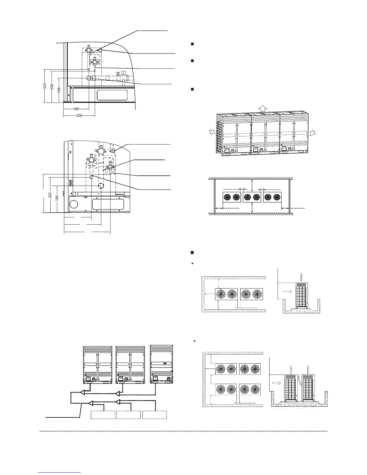
4.6 Installation space for outdoor unit
Ensure enough space for maintenance. The modules in the
same system must be on the same height.(see the Fig.4-8)
When installing the unit, leave a space for maintenance shown
in Fig.4-9. Install the power supply at the side of the outdoor
unit. For installation procedure, see the power supply device
Installation manual.
In case any obstacles exist above the outdoor unit, refer to
Fig.4-14.
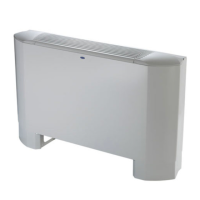
Fig.4-6-1
P1 amplification
Liquid side
Gas side
Gauge point
(Cooling only type without)
Oil balance pipe
(The connected pipe
diameter Φ15.9)
Detect the pressure/
Refrigerant replenishment
(The connected pipe
diameter Φ31.8)
For parallel connect
the modular units
Fig.4-10
Fig.4-11
4.7 Layout
When the outdoor unit is higher than the surrounding obstacle
One row
Tow rows
Fig.4-9
Top view of the outdoor unit
>1000mm
>1000mm
100mm~500mm
>1000mm
>1000mm
100mm~500mm
Fig.4-8
>1m
>1m
>1m
100-500mm
Front Front
>1m
>1m>1m
>1m
100-500mm
Front Front
Front Front
(Air-in ) (Air-in )
(Air-out )
Installation and maintenance surface
>800mm
>800mm
6
Installation manual
Fig.4-7
4.5 Outdoor units’ placement sequence &
master and slave units’ settings
A system, which provide with more than two outdoor units, will
be set as the followings method: The outdoor units in this
system should place sequentially from the large to the small
capacity; the largest capacity outdoor unit must be mounted at
the first branch joint site; and set the largest capacity outdoor
unit address as the master Unit, while the other setting as the
Slave Unit. Take 38HP (composed by 10HP, 12HP and 16HP)
as an example:
1) Place the 16HP at a side of the first branch joint site.
2) Place the unit from the large capacity to the small (See the
detail placement illustration)
3) Set 16HP as the main unit, while the 12HP and the 10HP
as the aux. unit.
+3 +3 +3
The 1st branch joint
Outdoor unit
(38HP)
Indoor unit A Indoor unit B Indoor unit C
Gauge point
(Cooling only type without)
Fig.4-6-2
P2 amplification
Detect the pressure/
Refrigerant replenishment
Gas side
(The connected pipe
diameter Φ31.8)
Oil balance pipe
For parallel connect
the modular units
Liquid side
(The connected pipe
diameter Φ19.1)
12HP, 14HP, 16HP
18HP
 Loading...