Do you have a question about the Carrier SYSTXCCUID01-B and is the answer not in the manual?
| Type | Control Panel |
|---|---|
| Model Number | SYSTXCCUID01-B |
| Brand | Carrier |
| Color | White |
| Connectivity | Wi-Fi |
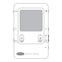
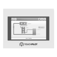
| Display | Touchscreen |
| Compatibility | Carrier Infinity System |
| Control Features | Programmable |
| Features | Energy monitoring, remote access |
Learn about safety symbols like DANGER, WARNING, and CAUTION to prevent personal injury.
Guidelines for selecting the Infinity Control location and wiring considerations.
Information on mounting plastic options and decorative backplates for the Infinity Control.
Details on the ABCD wire connector and recommended color coding for system wiring.
Proper wiring procedures for installing humidifiers and ventilators.
Configuring outdoor unit type, size, and electric heater settings.
Navigating screens to select air filter type, humidifier, and UV lights.
Reviewing equipment summary and initiating the system installation process.
Adjusting furnace airflow and staging parameters for optimal comfort.
Configuring G terminal operation and high stage timer for furnace control.
Setting heat pump outdoor lockouts and defrost behavior.
Configuring utility saver input and understanding checkout procedures.
Viewing equipment status, system faults, and event history.
Understanding features like continuous fan, compressor timeguard, and staging timers.
Specific operational considerations for hybrid and hydronic heat systems.
Checking current system status and re-initiating the installation process.
Detailed list of fault codes for fan coil, furnace, outdoor unit, and user interface.