GB - 4
Type C Electronic Control
"Dip-switch" functions (microswitches)
Dip-switch 1
In open contact position, it allows to activate the frost protection
function (
).
Dip-switch 2
In open contact position, it permits the fan operation at the selected
URGGFGXGPKHVJGUGVRQKPVVGORGTCVWTGKUUCVKUſGF
Dip-switch 3
In open contact position, it restricts the range of the temperature
selection knob according to the following limits:
Cooling: minimum selectable temperature: 23°C.
Heating: maximum selectable temperature: 21°C.
Dip-switch 4
In open contact position, it permits to activate the fan periodically
GXGPKHVJGUGVRQKPVVGORGTCVWTGKUUCVKUſGFCKTUCORNKPI
'LSVZLWFKFRQÀJXUDWLRQPLFURVZLWFKHV
Dip-switch 1
Closed Frost protection (
) disabled.
Open Frost protection (
) enabled.
Dip-switch 2
Closed Ventilation controlled by thermostat.
Open Continuous ventilation.
Dip-switch 3
Closed Temperature block disabled.
Open Temperature block enabled.
Dip-switch 4
Closed "Air sampling" disabled.
Open "Air sampling" enabled.
Dip-switch 5
No function for this model.
Dip-switchs 6, 7 and 8
The position of these dip-switches regulates the control current of
the motor. A higher voltage corresponds to a higher speed of the
fan. The selection is made according to the following table:
Control
NOTE: Factory setting is with all dip-switches in close position.
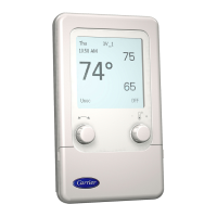
Use of temperature sensor
Internal sensor:
This is used in all installations where the control is wall-mounted.
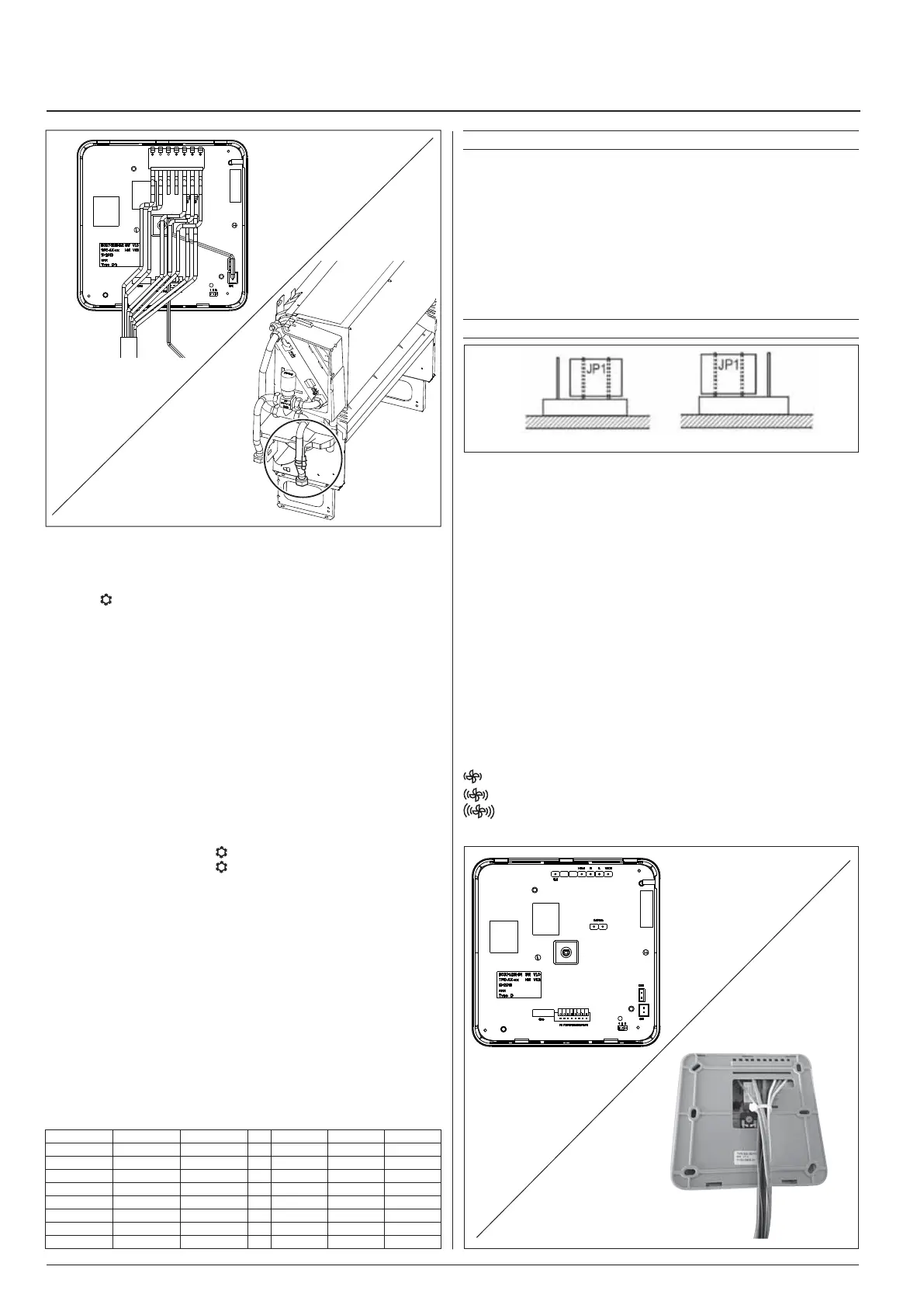
6QCEVKXCVGKVENQUGLWORGT,2CUUJQYPKPſIWTG#CPFQPVJG
electronic board screenprint.
Remote sensor:
This is used on all installations with unitmounted control. It is positioned
on the return air, close to the fan. To activate it, close jumper JP1 as
UJQYPKPſIWTG$CPFQPVJGGNGEVTQPKEDQCTFUKNMUETGGPRTKPVKPI
NOTE: Factory setting is with activated internal sensor.
Diagnostic warnings
The following alarm situations are indicated:
'HIHFWLYHVHQVRUVWKHUHG/('ÁDVKHV
Possible causes:
ŖHCKNWTGQTUJQTVEKTEWKVQHKPVGTPCNUGPUQT
ŖHCKNWTGQTUJQTVEKTEWKVQHYCVGTVGORGTCVWTGUGPUQT
,QFRUUHFWFRQÀJXUDWLRQ
7KHJUHHQ/('ÁDVKHVHYHU\5 seconds.
This happens when:
ŖKPEQPVTQNDQVJEGPVTCNKUGFUGCUQPCNEJCPIGQXGTUKIPCNUő4%CPF
4*ŒCTGGPCDNGF
Autotest
6JGő#WVQVGUVŒHWPEVKQPKUCEVKXCVGFD[JQNFKPIVJGUGCUQPCN
changeover button pressed and at the same time pressing the
speed selection button three times within 1 second. In this way it is
possible to check the starting of all fan coils.
6JGDNWGCPFTGF.'&UYKNNDGIKPVQƀCUJ'CEJQHVJGXCTKQWUWPKVU
will be activated for 10 seconds in the following sequence:
Low fan speed.
Medium fan speed.
*KIJHCPURGGF
CV Motorized cold-water valve.
Fig. 6
Fig. 7
321
321
Fig. A Fig. BInternal sensor 4GOQVGUGPUQT
Jumper 1 Jumper 2 Jumper 3 LOW MID HIGH
Closed Closed Closed
Æ
2V 6V 10V
Closed Closed Open
Æ
2V 4V 6V
Closed Open Closed
Æ
6V 8V 10V
Closed Open Open
Æ
2V 3V 4V
Open Closed Closed
Æ
8V 9V 10V
Open Closed Open
Æ
5V 6V 7V
Open Open Closed
Æ
4V 6V 8V
Open Open Open
Æ
3V 6V 9V
Fig. 8
Fig. 9
 Loading...