21
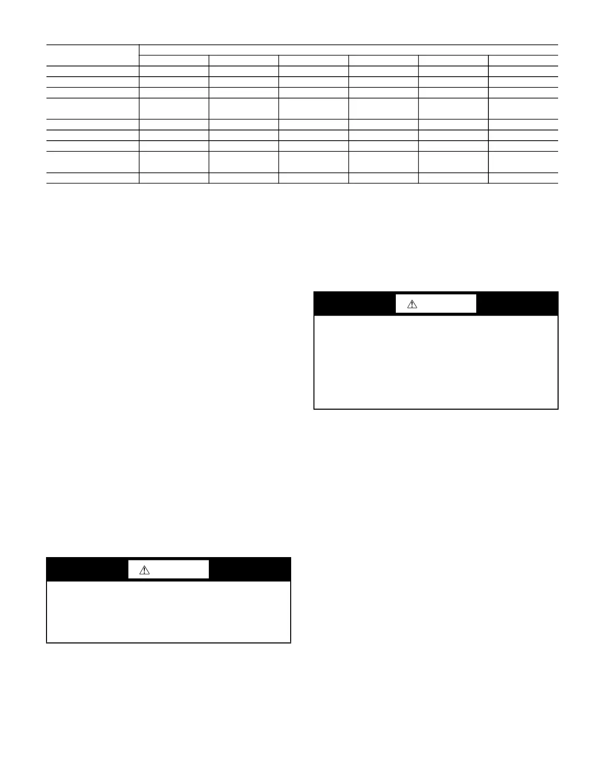
Table 2 — Operating Weights
* Humidi-MiZer is not available on 48TC*M models.
SLAB MOUNT (HORIZONTAL UNITS ONLY)
Provide a level concrete slab that extends a minimum of 6-in.
(150 mm) beyond unit cabinet. Install a gravel apron in front of
condenser coil air inlet to prevent grass and foliage from obstruct-
ing airflow.
NOTE: Horizontal units may be installed on a roof curb if
required.
ALTERNATE UNIT SUPPORT (IN LIEU OF CURB OR
SLAB MOUNT)
A non-combustible sleeper rail can be used in the unit curb sup-
port area. If sleeper rails cannot be used, support the long sides
of the unit with a minimum of 3 equally spaced 4-in. x 4-in.
(102 mm x 102 mm) pads on each side.
Step 5 — Field Fabricate Ductwork
NOTE: Cabinet return-air static pressure (a negative condition)
shall not exceed 0.35 in. wg (87 Pa) with economizer or
0.45 in. wg (112 Pa) without economizer.
For vertical ducted applications, secure all ducts to roof curb and
building structure. Do not connect ductwork to unit.
Fabricate supply ductwork so that the cross sectional dimensions
are equal to or greater than the unit supply duct opening dimen-
sions for the first 18-in. (458 mm) of duct length from the unit
basepan.
Insulate and weatherproof all external ductwork, joints, and roof
openings with counter flashing and mastic in accordance with ap-
plicable codes.
Ducts passing through unconditioned spaces must be insulated
and covered with a vapor barrier.
If a plenum return is used on a vertical unit, the return should be
ducted through the roof deck to comply with applicable fire codes.
A minimum clearance is not required around ductwork.
Step 6 — Rig and Place Unit
Keep unit upright and do not drop. Spreader bars are required for
07-14 size units; size 16 units do not require spreader bars. Rollers
may be used to move unit across a roof. Level by using unit frame
as a reference. See Table 2 and Fig. 15 for additional information.
Lifting holes are provided in base rails as shown in Fig. 15. Refer
to rigging instructions on unit.
Rigging materials under unit (cardboard or wood to prevent base
pan damage) must be removed PRIOR to placing the unit on the
roof curb.
When using the standard side drain connection, ensure the red
plug in the alternate bottom connection is tight. Do this before set-
ting the unit in place. The red drain pan can be tightened with a
1
/
2
-in. square socket drive extension. For further details see Install
External Condensate Trap and Line on page 30.
Before setting the unit onto the curb, recheck gasketing on curb.
48TC
UNITS — lb (kg)
07 08 09 12 14 16
48TC*A 652 (296)
48TC*M 777 (353) 805 (365) 850 (386)
48TC*D 900 (408) 970 (440) 980 (444) 1075 (487) 1305 (592)
Economizer
Vertical 50 (23) 75 (34) 75 (34) 75 (34) 75 (34) 130 (47)
Horizontal 80 (36) 122 (55) 122 (55) 122 (
55) 122 (55) 242 (110)
Humidi-MiZer
®
System* 41 (15) 80 (36) 80 (36) 80 (36) 85 (39) 90 (41)
Powered Outlet 35 (16) 35 (16) 35 (16) 35 (16) 35 (16) 35 (16)
Curb
14-in. (356 mm) 110 (50) 143 (65) 143 (65) 143 (65) 143 (65) 180 (82)
16-in. (610 mm) 145 (66) 245 (111) 245 (111) 245 (111) 245 (111) 255 (116)
CAUTION
PROPERTY DAMAGE HAZARD
Failure to follow this caution may result in damage to roofing
materials.
Membrane roofs can be cut by sharp sheet metal edges. Be
careful when placing any sheet metal parts on such roof.
CAUTION
UNIT DAMAGE HAZARD
Failure to follow this caution may result in equipment damage.
All panels must be in place when rigging. Unit is not designed
for handling by fork truck when packaging is removed.
If using top crate as spreader bar, once unit is set, carefully
lower wooden crate off building roof top to ground. Ensure
that no people or obstructions are below prior to lowering the
crate.
 Loading...


