53
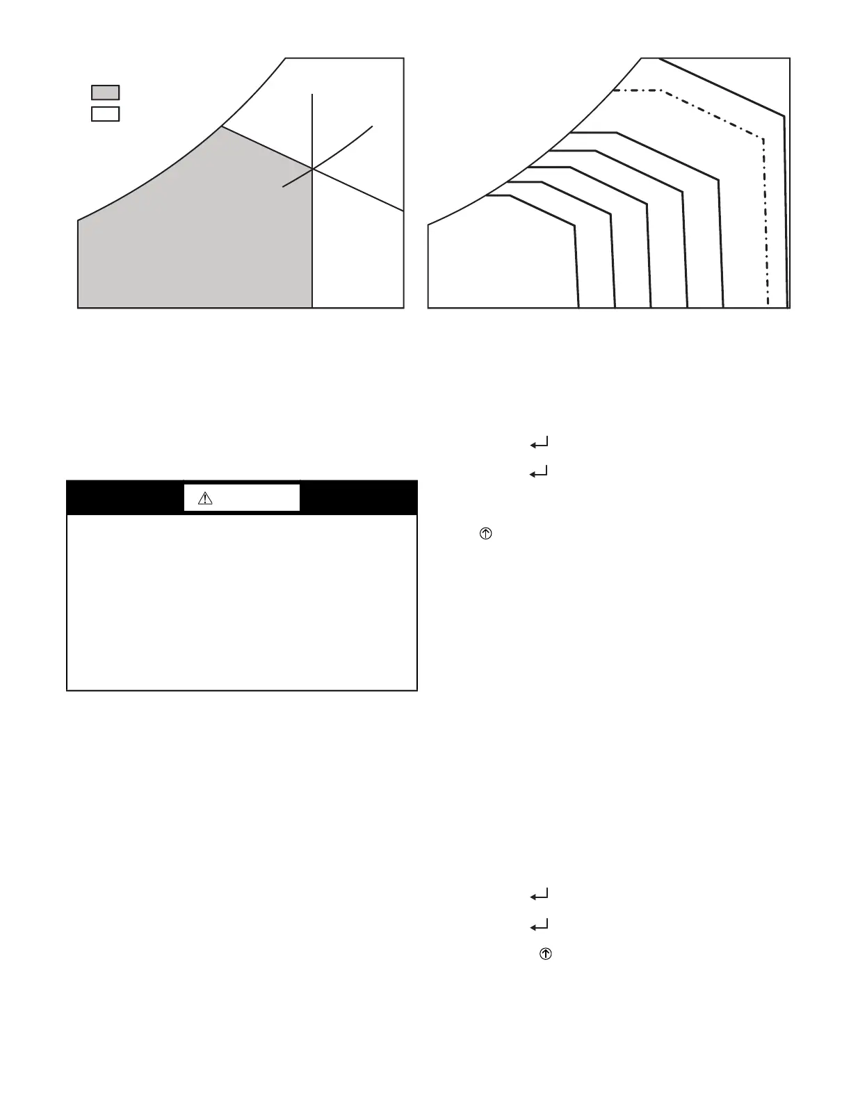
Fig. 77 — Single Enthalpy Curve Boundaries
CHECKOUT
Inspect all wiring connections at the economizer module’s termi-
nals, and verify compliance with the installation wiring diagrams.
For checkout, review the Status of each configured parameter and
perform the Checkout tests.
NOTE: For information about menu navigation and use of the
keypad, see Interface Overview on page 44.
Power Up
After the W7220 module is mounted and wired, apply power.
Initial Menu Display
On initial start up, Honeywell displays on the first line and Econo-
mizer W7220 on the second line. After a brief pause, the revision
of the software appears on the first line and the second line will be
blank.
Power Loss (Outage or Brownout)
All set points and advanced settings are restored after any power
loss or interruption.
NOTE: All settings are stored in non-volatile flash memory.
Status
Use the Status menu (see Table 12) to check the parameter values
for the various devices and sensors configured.
NOTE: For information about menu navigation and use of the
keypad, see Interface Overview on page 44.
Checkout Tests
Use the Checkout menu (on page 47) to test the damper operation
and any configured outputs. Only items that are configured are
shown in the Checkout menu.
NOTE: For information about menu navigation and use of the
keypad, see Interface Overview on page 44.
To perform a Checkout test:
1. Scroll to the desired test in the Checkout menu using the
▲ and ▼ buttons.
2. Press the (Enter) button to select the item.
3. RUN? appears.
4. Press the (Enter) button to start the test.
5. The unit pauses and then displays IN PROGRESS.
6. When the test is complete, DONE appears.
7. When all desired parameters have been tested, press the
(Menu Up) button to end the test.
The Checkout tests can all be performed at the time of installation
or at any time during the operation of the system as a test that the
system is operable.
TROUBLESHOOTING
Alarms
The economizer module provides alarm messages that display on
the 2-line LCD.
NOTE: Upon power up, the module waits 60 minutes before
checking for alarms. This allows time for all the configured devic-
es (e.g. sensors, actuator) to become operational. The exception is
the SAT sensor which will alarm immediately.
If one or more alarms are present and there has been no keypad ac-
tivity for at least 5 minutes, the Alarms menu displays and cycles
through the active alarms.
You can also navigate to the Alarms menu at any time.
Clearing Alarms
Once the alarm has been identified and the cause has been re-
moved (e.g. replaced faulty sensor), the alarm can be cleared from
the display.
To clear an alarm, perform the following:
1. Navigate to the desired alarm.
2. Press the (Enter) button.
3. ERASE? displays.
4. Press the (Enter) button.
5. ALARM ERASED displays.
6. Press the (Menu up/Exit) button to complete the
action and return to the previous menu.
NOTE: If the alarm still exists after clearing it, it is redisplayed
within 5 seconds.
ECONOMIZING
AVAILABLE
NOT AVAILABLE
ENTHALPY
RA HUM (%RH)
RA TEMP
TEMPERATURE
ABSOLUTE HUMIDITY
ES5
ES4
ES3
ES2 ES1
HL
P1
(T,RH)
P2 (T,RH)
SINGLE ENTHALPY
DUAL ENTHALPY
HIGH LIMIT
WARNING
ELECTRIC SHOCK HAZARD
Failure to follow this warning could result in personal injury,
property damage, or death.
Before performing service or maintenance operations on unit,
always turn off main power switch to unit and install lock(s)
and lockout tag(s). Unit may have more than one power
switch. Ensure electrical service to rooftop unit agrees with
voltage and amperage listed on the unit rating plate.
If any wiring changes are required, first be sure to remove
power from the economizer module before starting work. Pay
particular attention to verifying the power connection (24 vac).
 Loading...


