30
4. Pressure-test all gas piping in accordance with local and
national plumbing and gas codes before connecting piping
to unit.
NOTE: Pressure test the gas supply system after the gas supply
piping is connected to the gas valve. The supply piping must be
disconnected from the gas valve during the testing of the piping
systems when test pressure is in excess of 0.5 psig (3450 Pa). Pres-
sure test the gas supply piping system at pressures equal to or less
than 0.5 psig (3450 Pa). The unit heating section must be isolated
from the gas piping system by closing the external main manual
shutoff valve and slightly opening the ground-joint union.
Check for gas leaks at the field-installed and factory-installed
gas lines after all piping connections have been completed. Use
soap-and-water solution (or method specified by local codes
and/or regulations).
NOTE: If orifice hole appears damaged or it is suspected to have
been re-drilled, check orifice hole with a numbered drill bit of cor-
rect size. Never re-drill an orifice (see Fig. 43). A burr-free and
squarely aligned orifice hole is essential for proper flame charac-
teristics.
Fig. 43 — Orifice Hole
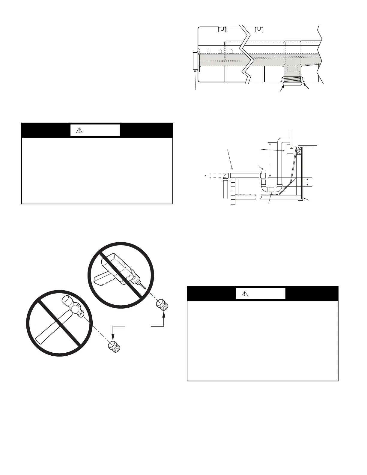
Step 11 — Install External Condensate Trap and
Line
The unit has one
3
/
4
-in. condensate drain connection on the end of
the condensate pan and an alternate connection on the bottom. See
Fig. 44. Unit airflow configuration does not determine which
drain connection to use. Either drain connection can be used with
vertical or horizontal applications.
To use the alternate bottom drain connection, remove the red drain
plug from the bottom connection (use a
1
/
2
-in. square socket drive
extension) and install it in the side drain connection.
The piping for the condensate drain and external trap can be com-
pleted after the unit is in place. See Fig. 44 and 45.
Fig. 44 — Condensate Drain Pan (Side View)
NOTE: If the alternate bottom drain is not used, check the drain
plug for tightness prior to setting the unit on the roof curb.
Fig. 45 — Condensate Drain Piping Details
All units must have an external trap for condensate drainage. In-
stall a trap at least 4-in. (102 mm) deep and protect against freeze-
up. If drain line is installed downstream from the external trap,
pitch the line away from the unit at 1-in. per 10 ft (25 mm in 3 m)
of run. Do not use a pipe size smaller than the unit connection
(
3
/
4
-in.).
Step 12 — Make Electrical Connections
NOTE: Field-supplied wiring shall conform with the limitations
of minimum 63°F (33°C) rise.
FIELD POWER SUPPLY (SIZES 07-14)
If equipped with optional powered convenience outlet: The power
source leads to the convenience outlet’s transformer primary are
not factory connected. Installer must connect these leads accord-
ing to required operation of the convenience outlet. If an always-
energized convenience outlet operation is desired, connect the
source leads to the line side of the unit-mounted disconnect.
(Check with local codes to ensure this method is acceptable in
WARNING
Failure to follow this warning could result in personal injury,
death and/or property damage.
• Connect gas pipe to unit using a backup wrench to
avoid damaging gas controls.
• Never purge a gas line into a combustion chamber.
• Never test for gas leaks with an open flame. Use a
commercially available soap solution made specifically
for the detection of leaks to check all connections.
• Use proper length of pipe to avoid stress on gas control
manifold.
BURNER
ORIFICE
WARNING
Failure to follow this warning could result in personal injury or
death.
Do not use gas piping as an electrical ground.
Unit cabinet must have an uninterrupted, unbroken electrical
ground to minimize the possibility of personal injury if an
electrical fault should occur. This ground may consist of elec-
trical wire connected to unit ground lug in control compart-
ment, or conduit approved for electrical ground when installed
in accordance with NEC (National Electrical Code); ANSI/
NFPA 70, latest edition (in Canada, Canadian Electrical Code
CSA [Canadian Standards Association] C22.1), and local elec-
trical codes.
DRAIN
(FACTORY-INSTALLED)
PLUG
CONDENSATE PAN (SIDE VIEW)
STANDARD
SIDE DRAIN
ALTERNATE
BOTTOM DRAIN
NOTE: Trap should be deep enough to offset maximum unit static
difference. A 4-in. (102 mm) trap is recommended.
MINIMUM PITCH
1˝ (25 mm) PER
10´ (3 m) OF LINE
BASE RAIL
OPEN
VENT
TO ROOF
DRAIN
DRAIN PLUG
ROOF
CURB
SEE NOTE
3˝ (76 mm)
MIN
 Loading...


