36
equipped) or to the external disconnect (through unit side panel).
A hole must be field cut in the main control box bottom on the left
side so the 24-v control connections can be made. Connect the
control power conduit to the unit control box at this hole.
Units Without Thru- Base Connections
1. Install power wiring conduit through side panel openings.
Install conduit between disconnect and control box.
2. Install power lines to terminal connections as shown in
Fig. 60.
Voltage to compressor terminals during operation must be within
voltage range indicated on unit nameplate. On 3-phase units, volt-
ages between phases must be balanced within 2% and the current
within 10%. Use the formula on page 33 to determine the percent
of voltage imbalance. Operation on improper line voltage or ex-
cessive phase imbalance constitutes abuse and may cause damage
to electrical components. Such operation would invalidate any ap-
plicable Carrier warranty.
Field Control Wiring
The 48TC unit requires an external temperature control device.
This device can be a thermostat (field-supplied) or a PremierLink
controller (available as factory-installed option or as field-installed
accessory, for use on a Carrier Comfort Network
®
or as a stand-
alone control) or the RTU Open Controller for Building Manage-
ment Systems using non-CCN protocols (RTU Open is available
as a factory-installed option only).
Thermostat
Install a Carrier-approved accessory 2-stage thermostat according
to installation instructions included with the accessory. For com-
plete economizer function and 2-stage compressor operation, se-
lect a two-stage cooling thermostat. If a 2-stage cooling thermostat
is not available, use a single stage cooling thermostat instead, but
note that this will limit cooling to just 1 stage. Locate the thermo-
stat accessory on a solid wall in the conditioned space to sense av-
erage temperature in accordance with the thermostat installation
instructions. If the thermostat contains a logic circuit requiring
24-v power, use a thermostat cable or equivalent single leads of
different colors with minimum of seven leads (see Fig. 62). If the
thermostat does not require a 24-v source (no “C” connection
required), use a thermostat cable or equivalent with minimum of
six leads. Check the thermostat installation instructions for addi-
tional features which might require additional conductors in the
cable. For wire runs up to 50 ft. (15 m), use no. 18 AWG (Ameri-
can Wire Gage) insulated wire [35°C (95°F) minimum]. For 50 to
75 ft. (15 to 23 m), use no. 16 AWG insulated wire [35°C (95°F)
minimum]. For over 75 ft. (23 m), use no. 14 AWG insulated wire
[35°C (95°F) minimum]. All wire sizes larger than no. 18 AWG
cannot be directly connected to the thermostat and will require a
junction box and splice at the thermostat.
Fig. 62 — Low-Voltage Connections
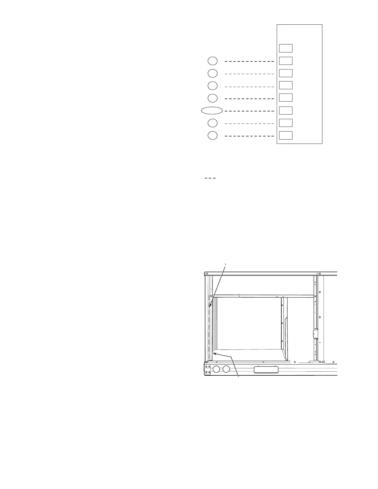
Unit Without Thru-Base Connection Kit
Pass the thermostat control wires through the hole provided in the
corner post; then feed the wires through the raceway built into the
corner post to the control box. Pull the wires over to the terminal
strip on the upper-left corner of the Controls Connection Board.
See Fig. 63.
NOTE: If thru-the-bottom connections accessory is used, refer to
the accessory installation instructions for information on routing
power and control wiring.
Fig. 63 — Field Control Wiring Raceway
(Sizes 07-14 Only)
FACTORY-OPTION THRU-BASE CONNECTIONS (ELEC-
TRICAL CONNECTIONS) (SIZE 16)
This service connection kit consists of a
1
/
2-
in. electrical bulkhead
connector and a 1
1
/
2
-in. electrical bulkhead connector, connected
to an “L” bracket covering the embossed (raised) section of the
unit basepan in the condenser section. See Fig. 64. The
1
/
2
-in.
bulkhead connector enables the low-voltage control wires to pass
through the basepan. The 1
1
/
2
-in. electrical bulkhead connector al-
lows the high-voltage power wires to pass through the basepan.
X
C
G
W2
C
W2
G
W1
O/B/Y2
Y2
R
W1
R
Y1
Y1
T
H
E
R
M
O
S
T
A
T
(NOTE 1) (NOTE 2)
CENTRAL
TERMINAL
BOARD
TYPICAL
THERMOSTAT
CONNECTIONS
NOTES:
1. Typical multi-function marking. Follow manufacturer’s configuration
instructions to select Y2. Do not configure for O output.
2. Y2 to Y2 connection required on single-stage cooling units when
integrated economizer function is desired.
Field-Wiring
RACEWAY
HOLE IN END PANEL (HIDDEN)
 Loading...


