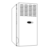
7
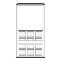
Dimensions
A98520
DIMENSIONS (In.)
*
Refer to the furnace Installation Instructions for proper venting procedures.
† Oval collar
UNIT
SIZE A D
E
VENT
CONN
*
(Dia)
040-12
14-3/16 12-9/16 12-11/16 4
060-08
14-3/16 12-9/16 12-11/16 4
060-12
14-3/16 12-9/16 12-11/16 4
080-14
17-1/2 15-7/8 16 4
080-16
21 19-3/8 19-1/2 4
100-12
17-1/2 15-7/8 16 4
100-16
21 19-3/8 19-1/2 4
100-20
24-1/2 22-7/8 23 4
120-16
21 19-3/8 19-1/2 5†
120-20
24-1/2 22-7/8 23 5†
135-20
24-1/2 22-7/8 23 5†
A
D
13
⁄16″
E
11
⁄16″
11
⁄16″
28
1
⁄2″
39
7
⁄8″
24
5
⁄16″
11
⁄16″
3″
2
1
⁄16″
1″
12
5
⁄16″
5
3
⁄8″
5
13
⁄16″
2
3
⁄8″
AIR INLET
7
⁄8-IN. DIA HOLE
POWER ENTRY
7
⁄8-IN. DIA
ACCESSORY
1
3
⁄4-IN. DIA HOLE
GAS ENTRY
1
⁄2-IN. DIA HOLE
THERMOSTAT
WIRE ENTRY
SIDE INLET
VENT CONN
1. Two additional
7
⁄8-in. dia holes are located in the top plate.
2. Minimum return-air openings at furnace, based on metal duct. If flex duct is used,
see flex duct manufacturer's recommendations for equivalent diameters.
3. Minimum return-air opening at furnace:
a. For 800 CFM–16-in. round or 14
1
⁄2 x 12-in. rectangle.
b. For 1200 CFM–20-in. round or 14
1
⁄2 x 19
1
⁄2-in. rectangle.
c. For 1600 CFM–22-in. round or 14
1
⁄2 x 23
1
⁄4-in. rectangle.
d. For airflow requirements above 1800 CFM, see Air Delivery table in Product Data literature for specific
use of single side inlets. The use of both side inlets, a combination of 1 side and the bottom, or the
bottom only will ensure adequate return air openings for airflow requirements above 1800 CFM.
NOTES:
5
3
⁄8″
5
13
⁄16″
2
3
⁄8″
2
11
⁄16″
1″
2
1
⁄16″
19″
13
⁄16″
7
⁄8-IN. DIA
POWER ENTRY
AIRFLOW
OUTLET
1
1
⁄2-IN. DIA
R.H. GAS ENTRY
7
⁄8-IN. DIA ACCESSORY
1
⁄2-IN. DIA THERMOSTAT
WIRE ENTRY
SIDE INLET
14
1
⁄2″
1″
23
1
⁄4″
SIDE RETURN
DUCT LOCATION
1
3
⁄4″
TYP 1″
5
⁄8″
TYP

 Loading...