Electrical Wiring
• The dipswitch is dialled to “On” position with the overline strapping if the code or overline status is “1”. The
dipswitch is dialled to “O’’ position with the overline if the code or overline status is “O”.
• In the table below, the choice in the box “ refers to the setting of the socket/over-line before delivery.
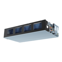
Indoor Units PCB
In the following table, 1 represents ON and 0 represents OFF.
Denition principles of code switches:
SW01 is used to set the capabilities of master and slave indoor units as well as the indoor unit; SW03 is used to
set indoor unit address (combine original communication address and address of centralized controller).
SW08 is usedset room card and 26
o
C lock.
(A) Denition and description of SW01
Note 1: A wired controller can be connected to at most 16 ultra thin air-duct indoor units.
Dipswitch Setting
SW01_1
Operation
mode
displayed
on wired
controller
1
0
[air supply] [refrigerating] [dehumidication]
[automatic] [air supply] [refrigerating] [dehumidication] [heating]
SW01_2
SW01_3
SW01_4
Address of
wire
controlled
indoor unit
(Note 1)
[2] [3] [4] Address of wire controlled indoor unit (group address)
0 0 0 0# (wire-controlled master unit) (default)
0 0 1 1# (wire-controlled slave unit)
0 1 0 2# (wire-controlled slave unit)
0 1 1 3# (wire-controlled slave unit)
1 0 0 4# (wire-controlled slave unit)
1 0 1 5# (wire-controlled slave unit)
1 1 0 6# (wire-controlled slave unit)
1 1 1 7# (wire-controlled slave unit)
SW01_5
SW01_6
SW01_7
SW01_8
Capability of
indoor unit
[5] [6] [7] [8] Capability of indoor unit
0 0 0 0 0.6HP
0 0 0 1 0.8HP
0 0 1 0 1.0HP
0 0 1 1 1.2HP
0 1 0 0 1.5HP
0 1 0 1 1.7HP
0 1 1 0 2.0HP
0 1 1 1 2.5HP
1 0 0 0 3.0HP
1 0 0 1 3.2HP
1 0 1 0 4.0HP
1 0 1 1 5.0HP
1 1 0 0 6.0HP
1 1 0 1 8.0HP
1 1 1 0 10.0HP
1 1 1 1 15.0HP
19
 Loading...
