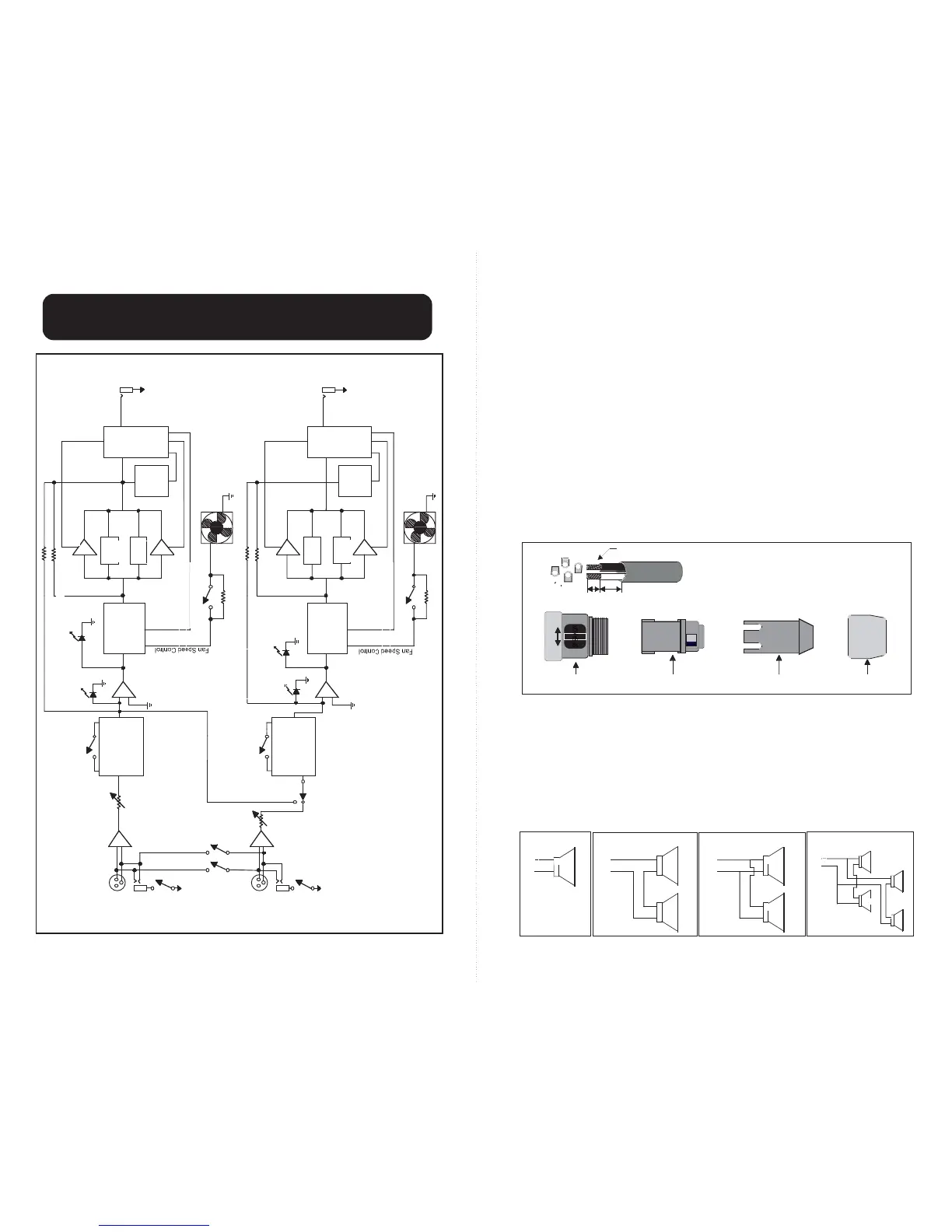
F-SERIES AMPLIFIER BLOCK DIAGRAM
BLOCK DIAGRAM
MONO “Y” INPUT MODE
This feature allows both channels of the amplifier to be driven from a single input. To use
this feature, plug one speaker cabinet into any of the channel 1 speaker output connectors
and a second cabinet into any of the channel 2 speaker output connectors. Next, set the
Accessory Group switches labeled “PARALLEL INPUTS” to their right-most position (as
viewed from the rear of the amplifier). Now, signal entering any input will be available on
both channels. The channel 1 level control will affect speakers connected to channel 1’s out-
put and channel 2 level will control speakers on channel 2’s outputs. This feature is also
used to “daisy chain” from one piece of equipment to the next (since channel 1 and channel 2
inputs are placed in parallel, any signal present on one will be available at the other).
OUTPUT CONNECTIONS
There are two 1/4” phone jacks available for speaker connections (one for each channel).
Additionally, there are two pairs of binding posts that not only allow for high current con-
nections to speakers but are also used when “bridging” the outputs (see section titled
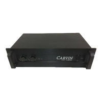
“Bridging the Amp”). Carvin supplies another alternative for connecting speakers to an
F1200. Widely acclaimed audio connector manufacturer “Neutrik”, created a standard for
speaker connections that provides high current capacity and ease of use. These connec-
tors, dubbed ”Speakons”, have been embraced by professionals as an improvement over
previous standards.
As shown above, standard Speakon speaker cables are wired to pins 1+ and 1-. Pins 2+
and 2- are reserved for use when biamping (as is the case on Carvin TR1503 and TR1801
trapezoidal speaker systems), or bridging (not supported).
Make sure to use heavy gauge wire for all speaker connections (no lighter than 16 gauge
up to 50’, like Carvin’s PH50). Caution: never use shielded cable (i.e., guitar cable) to
connect speakers. It poses an abnormal load on any audio power amplifier and its imped-
ance will not provide an adequate current path for the speakers.
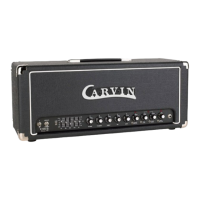
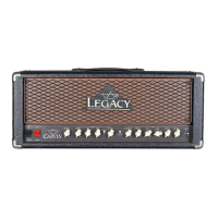
TYPICAL LOUDSPEAKER IMPEDANCE CONFIGURATIONS
Individual speakers or speaker cabinet wiring examples.