5 18
One or both clip
LED’s flash intermit-
tently
Sound is coming from
both channels when
only one channel has
signal at its input
Unit enters PROTECT
mode repeatedly after
resets
Input signal
Accessory Group’s
“Parallel Inputs” switch-
es are in the mono
position
Accessory Group’s
“BRIDGE MONO”
switches are in the
mono position
Excessive speaker load
Shorted speaker or
speaker cable
Program material con-
tains excessive signal
below 20Hz
Clip LED’s light to indi-
cate maximum output
level. This is not a
problem as long as the
LED’s don’t stay contin-
uously lit and the sound
is not distorted.
Running the system
with the LED’s continu-
ously lit will not harm
the power amp but is
dangerous to speakers
whose power ratings
are not well above the
amplifier’s power rating.
Move “Parallel Inputs”
switches to the Stereo
position.
Move “BRIDGE
MONO” switches to the
Stereo position.
Verify that the total
speaker load is not less
than the amplifiers rat-
ing. (i.e., three 4Ω
speakers per channel
is less than 2Ω total.)
Try different cables and
speakers
Move Accessory Group
“Sub Filters” switches
to the ON position.
CorrectionProblem Possible Cause
TECHNICAL ASSISTANCE
If the above chart has not been able to guide you to the problem then answer the follow-
ing five questions:
1. AC cord attached to a source ‘alive’ with appropriate Voltage and current capacity?
2. Is the fuse OK and power switched on?
3. Correct level audio signal connected to inputs through known good cables?
4. Are the Accessory Group switches set properly and level controls raised sufficiently?
5. Are known good speakers connected properly using known good cables?
Carvin’s friendly technical support staff will be happy to assist by calling 800-854-2235.
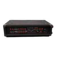
1. CHANNEL 1 1/4” PHONE JACK INPUT
This stereo phone jack is designed to receive either balanced or unbalanced input sig-
nals. Balanced signals coming into this jack should be wired with the connector’s tip going
to signal + and the connector’s ring to signal -. The connector’s sleeve is then tied inter-
nally to ground through the GROUND LIFT switch.
2. CHANNEL 1 XLR INPUT CONNECTOR
Like the 1/4” phone jack, this input connector will accept either balanced or unbalanced
signals. Pin 2 is signal +, pin 3 signal - and pin 1 is grounded through the GROUND LIFT
switch.
3. CHANNEL 1 SPEAKON OUTPUT
The Speakon speaker connectors’ twist-lock design and high current capacity is a great
way to simplify speaker connection while maintaining a high, system wide damping factor.
(F1200 only).
4.
CHANNEL 1 1/4” PHONE JACK SPEAKER OUTPUT
Standard 1/4” phone jacks are supplied for convenient speaker connection.
5. CHANNEL 1 BINDING POST SPEAKER OUTPUT
An alternative for connecting speakers is through the binding posts. RED is positive and
BLACK is negative. These high current connectors will safely clamp bare wires at their
base or will accept standard banana plugs. (The two RED binding posts are used for mono
bridging, ch1 is + and ch2 is -).
6. RMS POWERMAX™ IMPEDANCE MATCHING SWITCH
Set this switch to the position that corresponds to the speaker load. (F1200 model only.
See the section “RMS POWERMAX™” for more information.)
7. MAIN POWER FUSE
Should the fuse ever blow, replace only with same type and value (see “Fuse Selection”).
F300 3A @ 120VAC or 1 1/2A @ 230VAC, Slow Blow
F600 6A @ 120VAC or 3A @ 230VAC, Slow Blow
F1200 12A @ 120VAC or 6A @ 230VAC, Slow Blow
(Note: Some F-Series amplifiers are supplied with circuit breakers. Should one of these
ever blow, simply let the breaker cool down and press to reset.)
REAR PANEL FEATURES