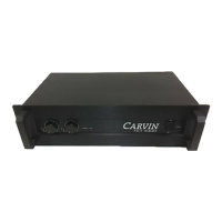
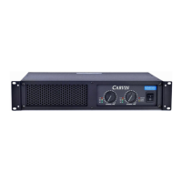
7. POWER INDICATOR
An orange LED unmistakably tells when the amplifier is turned on. (The various front
panel indicators were deliberately given different colors so the operator can see the status
of the amplifier from across the room with only a glance.)
8. CHANNEL 2 LEVEL CONTROL
A precision 41 step input level attenuator is used to adjust volume levels.
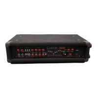
9. CHANNEL 2 SIGNAL INDICATOR
This green LED comes on when signal is present on channel 2.
10. CHANNEL 2 CLIP INDICATOR
This RED LED lights when channel 2 has reached its maximum output capability.
11. PROTECT INDICATOR
If the amplifier detects any problems due to abusive operating conditions, it will automati-
cally enter “PROTECT” mode. This mode will remove signal from one or both affected
channels and the “PROTECT” LED will light. (See the section entitled “PROTECT LED”
for more detailed information.)
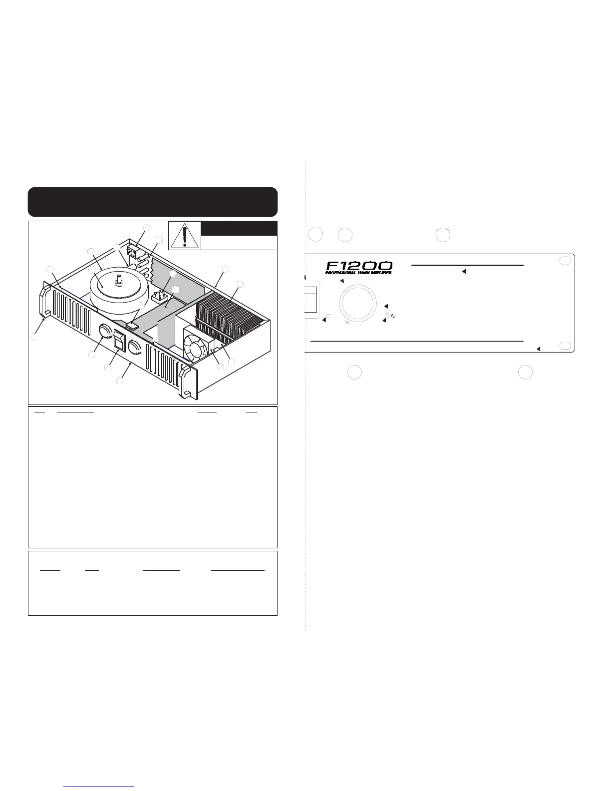
REF DESCRIPTION PART # QTY
1Switch, Impedance . . . . . . . . . . . . . . . . . . . . . . . . . . . . . . .25-31360 . . . . . . . . . .1
2Binding Post, Dual, Black/Red, Long . . . . . . . . . . . . . . . . .03-10450 . . . . . . . . . .2
3Bridge Rectifier, 35A . . . . . . . . . . . . . . . . . . . . . . . . . . . . .60-35040 . . . . . . . . . .1
4 Unichassis . . . . . . . . . . . . . . . . . . . . . . . . . . . . . . . . . . . . .10-06009 . . . . . . . . . .1
5Heatsink, custom, natural aluminum finish . . . . . . . . . . . .12-00504 . . . . . . . . . .2
6Bracket, Fan, Dual . . . . . . . . . . . . . . . . . . . . . . . . . . . . . . .10-10027* . . . . . . . . . .1
7Fan, DC 24V, 80mm, 36CFM . . . . . . . . . . . . . . . . . . . . . .70-02408 . . . . . . . . . .2**
8Front Panel . . . . . . . . . . . . . . . . . . . . . . . . . . . . . . . . . . . .10-06001-3 . . . . . . . . .1
9 Switch, Power . . . . . . . . . . . . . . . . . . . . . . . . . . . . . . . . . .25-31350 . . . . . . . . . .1
10 Knob, Power Amp . . . . . . . . . . . . . . . . . . . . . . . . . . . . . . .07-09001 . . . . . . . . . .2
11 Handle, Extruded, F-Series . . . . . . . . . . . . . . . . . . . . . . . .10-11120 . . . . . . . . . .2
12 Shield, Vent, F-Series . . . . . . . . . . . . . . . . . . . . . . . . . . . .10-06003 . . . . . . . . . .2
13 Mount, Toroid Cap . . . . . . . . . . . . . . . . . . . . . . . . . . . . . . .10-15004 . . . . . . . . . .1
Insulator, Toroid Pad (Not shown) . . . . . . . . . . . . . . . . . . .03-15010 . . . . . . . . . .2
14 Transformer, Power, Toroid . . . . . . . . . . . . . . . . . . . . . . . .See Chart . . . . . . . . . .1
15 Fuse Holder (See chart for fuse values) . . . . . . . . . . . . . .23-81116 . . . . . . . . . .1
16 Circuit Board Assembly (Includes all PCB’s) . . . . . . . . . . .80-12028 . . . . . . . . . .1
17 Capacitor, AC Line Switch . . . . . . . . . . . . . . . . . . . . . . . . .41-47322 . . . . . . . . . .1
18 Cover, Chassis (Not shown) . . . . . . . . . . . . . . . . . . . . . . .10-06005 . . . . . . . . . .1
19 Foot, .875x.3125 (Not shown) . . . . . . . . . . . . . . . . . . . . . .03-19682 . . . . . . . . . .4
20 Power Cord, AC, 16AWG (Not shown) . . . . . . . . . . . . . . .05-01604 . . . . . . . . . .1
* F1200 uses 10-10027 dual fan bracket, F300 & F600 uses 10-10017 single fan bracket.
** F1200 uses two fans whereas F300 and F600 uses only one.
Fuse/Transformer Selector Chart
Model
Line Fuse Value Transformer P/N
F1200.........120 VAC...........12A, 250V, Slow Blow . . . . . . .15-12120
F1200.........230 VAC............6A, 250V, Slow Blow . . . . . . .15-12240
F600..........120 VAC............6A, 250V, Slow Blow . . . . . . .15-06120
F600..........230 VAC............3A, 250V, Slow Blow . . . . . . .15-06240
F300..........120 VAC............3A, 250V, Slow Blow . . . . . . .15-03120
F300..........230 VAC.........1 1/2A, 250V, Slow Blow . . . . . .15-03240
CAUTION
RISK OF ELECTRIC SHOCK
THIS UNIT CONTAINS HIGH VOLTAGE
COMPONENTS INSIDE. REFER SERVICING
TO QUALIFIED SERVICE PERSONNEL.
REPLACEMENT PART GUIDE