167
Power switch is on
but LED doesn’t light
The unit has power
but no output is pre-
sent at the speakers
Loud hum coming
from speakers
Power plug is loose or
disconnected
Circuit breaker tripped
or fuse blown in circuit
fuse box
Amplifier fuse or circuit
breaker is blown
No input signal
Open speaker cable
Blown speaker fuse
Ground loop
Missing ground feed
(unbalanced only)
Reconnect plug.
Disconnect all other
loads on the same cir-
cuit and reset circuit
breaker or replace
fuse.
Disconnect the power
cord and replace fuse
only with same type
and value or reset cir-
cuit breaker.
Check that the source
equipment is properly
feeding the amplifier’s
input. The green signal
LED’s will show if sig-
nal is present.
Replace speaker cable
with a known good one.
Check speaker cabinet
for fuses and replace
as necessary
Move one or both
GROUND LIFT switch-
es (located in the
Accessory Group on
the rear panel) to the
left-most position.
(Note: Never defeat
the ground prong of the
AC power cord.
Serious shock or elec-
trocution may occur.)
Move one or both
GROUND LIFT switch-
CorrectionProblem Possible Cause
IN CASE OF TROUBLE
Every F-Series amplifier undergoes severe environmental “burn-in” as well as thorough
computer controlled and human testing. It is unlikely a malfunction will occur. However,
when something doesn’t seem to work properly, please refer to the following chart:
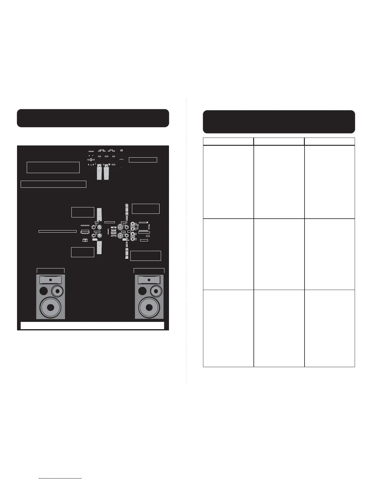
The following diagram illustrates the typical stereo setup. Although it shows XLR’s for
inputs and 1/4” phone plugs for outputs, a variety of alternative connectors are available
(see the following sections on “INPUT CONNECTIONS” and “OUTPUT CONNECTIONS”).
INPUT CONNECTIONS
The preferred method of connecting input signals is with balanced XLR’s (two conductors
plus a shield wire, such as Carvin’s XLR8). Balanced input signals provide the highest gain
and best noise rejection. 1/4” phone jacks are also capable of providing balanced input by
using a stereo plug (ring-, tip+ & sleeve gnd). However, not all sources provide balanced
outputs. In these cases an unbalanced 1/4” input is recommended (single conductor plus a
shield wire, such as Carvin’s SH2 or SH15).
MADE
AUS
IN THE
Toll Free 1-800-854-2235
WARNING –– To prevent a fire hazard, provide adequate space for ventilation! WARNING –– To prevent fire or
shock, do not expose to rain or moisture. WARNING –– Do not remove cover. No user-serviceable parts inside.
WARNING –– Replace fuse only with same type and value.
8
MONO
BRIDGE
–
+
+
–
INPUTS OUTPUTS
PARALLEL INPUTS
GROUND LIFT CH 1
GROUND LIFT CH 2
SUB FILTER CH 1
SUB FILTER CH 2
ACCESSORY GROUP
PIN 1– : GND (–)
PIN 2+ & 2– : NOT USED
PIN 1+ : SIGNAL (+)
CAUTION: TO PREVENT SHOCK, DO
NOT DEFEAT THE SAFETY GROUND.
SPEAKER IMPEDANCE
O
H
M
S
2
BRIDGE MONO
7
6
5
4
3
2
1
RMS POWERMAX
BALANCED LINE SPEAKER
®
ON OFF
LIFT GND
STEREO MONO
STEREO MONO
120VAC 50/60Hz 1400VA
FUSE = 12A SLOW BLOW
1
2
PIN 2 : SIGNAL (+)
PIN 3 : SIGNAL (–)
PIN 1 : GROUND
1
2
PROFESSIONAL STEREO
POWER AMPLIFIER
600/600 WATTS
2 OHMS MIN. IMPEDANCE
RMS POWERMAX®[ ]
O
H
M
S
4/8
FUSE
MON 1 EFF 1 EFF 2
BAL SENDS
LEFT/3 RIGHT/4 MAIN
R
POWER
L
SENDS
C
CNTRL
STEREO RETURNS
TAPE SEND
L R
B
A
MON 2
RM
LAMP
12V
SUB 1 PHONESSUB 2
Left Speaker Right Speaker
Left Speaker
Connector
Right Speaker
Connector
Left Input
Connector
Right Input
Connector
Mixer Output
Two conductors plus shield for
balanced input or one conductor
plus shield for unbalanced input.
Two conductor non-shielded, 16AWG
or larger, cable for speaker connections.