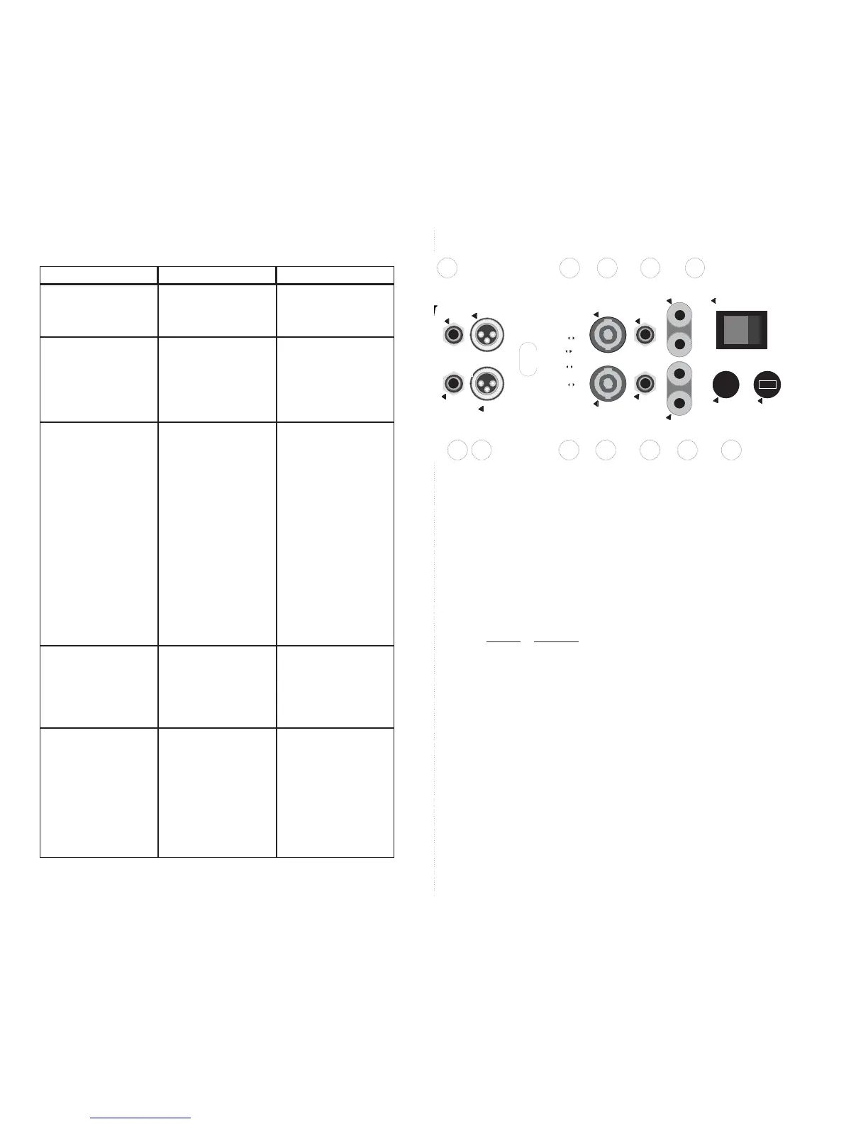
8. AC POWER CORD
Always use grounded (3 prong) outlets. Defeating the power cord’s ground connection
can result in electrocution. If the speakers produce hum caused by a ground loop, the loop
can be broken by opening the GROUND LIFT switches provided in the “ACCESSORY
GROUP”.
9. CHANNEL 2 BINDING POST SPEAKER OUTPUT
Performs the same function as channel 1’s binding posts. (See ➄.)
10.
CHANNEL 2 1/4” PHONE JACK SPEAKER OUTPUT
Performs the same function as channel 1’s jack. (See ➃.)
11.
CHANNEL 2 SPEAKON OUTPUT
Performs the same function as channel 1’s Speakon. (See ➂.)
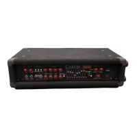
12. ACCESSORY GROUP SWITCHES
Use these switches to enable or defeat the following features:
SWITCH FUNCTION
1...........Parallel or ‘Y’ Inputs*
2...........Parallel or ‘Y’ Inputs*
3...........Channel 1 SUB FILTER (15Hz)
4...........Channel 2 SUB FILTER (15Hz)
5...........Channel 1 GROUND LIFT
6...........Channel 2 GROUND LIFT
7...........BRIDGE MONO**
8...........BRIDGE MONO**
* Switches 1 and 2 must be set in unison. For STEREO operation both must be in the left
position, for MONO, both right.
** Switches 7 and 8 must also be set in unison. Both left for STEREO and both right for
BRIDGE MONO.
13.
CHANNEL 2 XLR INPUT CONNECTOR
Performs the same function as channel 1’s XLR input. (See ②.)
14.
CHANNEL 2 1/4” PHONE JACK INPUT
Performs the same function as channel 1’s 1/4” input. (See ①.)
15. EXHAUST VENTS
These vents must have a minimum of 3” clearance to ensure adequate ventilation.
Blocking them will cause the amp to prematurely enter “PROTECT” mode.
Loud hum coming
from speakers
(cont’d)
No sound out of one
channel
One or both channels
cut out every few min-
utes
Sound is distorted
and clip indicator(s)
are on
Sound is distorted
and clip indicator(s)
are not on or only
flash occasionally
Bridge switch not set
properly
Unit entering PRO-
TECT mode due to
overheating
Program material con-
tains excessive signal
below 20Hz
Shorted speaker or
speaker cable
Too many speakers
Amplifier input signal is
too high
Defective input cable
es (located in the
Accessory Group on
the rear panel) to the
right-most position.
Make sure the bridge
switches (located in the
Accessory Group on
the rear panel) are set
to the position appropri-
ate for your setup.
Make sure both the
front and rear of the
amplifier has adequate
space for ventilation.
Verify that the total
speaker load is not less
than the amplifiers rat-
ing. (i.e., three 4Ω
speakers per channel
is less than 2Ω total.)
Check for shorted
speaker cables.
Move Accessory Group
“Sub Filters” switches
to the ON position.
Try different cables and
speakers
Try connecting one
speaker system at a
time.
Turn down the output
level of equipment
feeding the amplifier. If
the sound level is too
low then raise the con-
trols on the front of the
power amp.
Try substituting a
known good cable.
CorrectionProblem Possible Cause